MSD 6214 Midget DIS-2 Programmable Race Ignition Installation User Manual
Page 6
6
INSTALLATION INSTRUCTIONS
M S D
• W W W . M S D P E R F O R M A N C E . C O M • ( 9 1 5 ) 8 5 7 - 5 2 0 0 • F A X ( 9 1 5 ) 8 5 7 - 3 3 4 4
WIRING AND INSTALLATION
MOUNTING
The Ignition Control can be mounted in any position but should
be kept away from direct engine heat sources. It is fully potted with
a polyurethane compound and sealed. Make sure all of the wiring
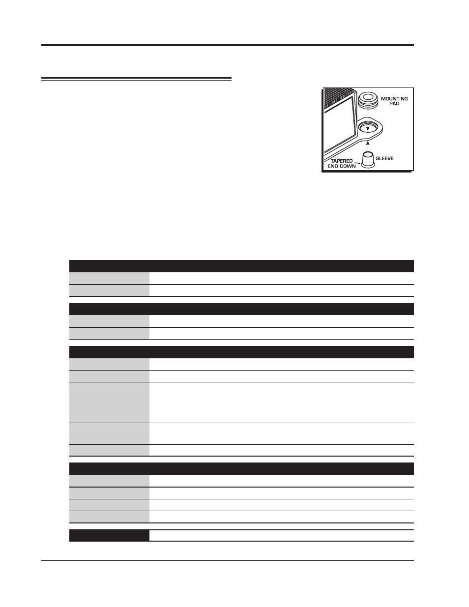
reaches their connecting components. Four rubber mounts and
sleeves are supplied for installation and should be installed to the
Control as shown in Figure 4.
With everything mounted, connect all of the wiring harnesses
and secure them away from engine heat sources. The magnetic
pickup harnesses each have a ground wire which should be con-
nected to engine ground.
WIRE FUNCTIONS
All of the wires, except the Power Leads, are supplied with Deutsch connectors already
terminated for a direct plug-in installation. It is not recommended to modify or lengthen any
wiring. Always route the wires away from direct heat sources and sharp edges. It is best to
route the trigger wires along a ground plane and away from the other wires.
Large 2-Pin Connector: Power Leads
Large Red
To the battery positive (+) terminal.
Large Black
To battery negative (-) terminal or a common engine ground
Small 2-Pin Connector:
Red/Green wire Connect to one side of the On/Off switch(+v source, internal fuse link)
Red wire
Connect to other side of the On/Off Switch
8-Pin Connector:
Violet/Green
Magnetic Pickup, channel 1 (Violet is +, Green is -)
LT Blue/LTGreen Magnetic Pickup, channel 2 (LT Blue is +, LT Green is -)
Dark Blue
This wire activates the Alternate Timing curve. When 12 volts are
applied, the Alternate Timing Curve is activated. When this wire is
removed from 12 volts the Alternate Curve is deactivated and timing
returns to the Run setting.
Gray
Tach output, 12 volt, 20°- 30°duration.
Note: Not compatible with
Magneto style Tachometers
Black
Tachometer ground wire
Coil Connector, 4-Pin:
Brown/White
Connects to the negative terminal of Coil 1
Brown/Green
Connects to the negative terminal of Coil 2
Brown/Orange Connects to the positive terminal of Coil 1
Brown/Orange Connects to the positive terminal of Coil 2
9-Pin connector
Interface connector (RS232) to a PC or PN 7550 Programmer
Figure 4 Installing the
Vibration Mounts.