MSD 6214 Midget DIS-2 Programmable Race Ignition Installation User Manual
Page 5
INSTALLATION INSTRUCTIONS
5
M S D
• W W W . M S D P E R F O R M A N C E . C O M • ( 9 1 5 ) 8 5 7 - 5 2 0 0 • F A X ( 9 1 5 ) 8 5 7 - 3 3 4 4
TRIGGER WHEEL FABRICATION
Due to the variety of engines and applications, a crank trigger wheel is not offered and must
be fabricated. The brackets for the two pickups must also be made.
The trigger wheel must be 3/8" thick for the MSD magnet to properly fit. The wheel can by
any type of non-magnetic material (aluminum, non-magnetic stainless, etc...) and can be any
diameter over 4”. MSD offers several trigger wheels for V8 applications that may be modified
for certain applica-
tions.
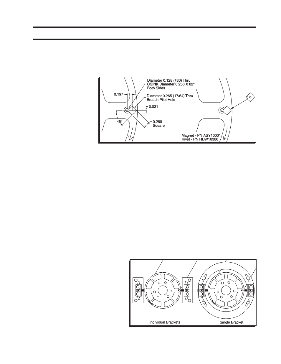
A magnet is sup-
plied that must
be installed in the
trigger wheel. This
magnet must be
oriented in one po-
sition to produce
the correct trigger
signal for the non
magnetic pickups.
This is detailed in
Figure 2.
1. Place the magnet in the wheel with the hole in the plastic overmolding facing the front of
the motor. The chamfer in the magnet must be positioned next to the hole for the aluminum
rivet.
2. Insert the aluminum rivet. The rivet must be set using a press or a vice with a set of smooth,
parallel jaws (such as the vice on a milling machine).
MOUNTING THE TRIGGER PICKUPS
Since the MSD Programmable Midget Ignition is a two channel, waste spark ignition system
there must be two trigger pickups. Brackets must be fabricated so the pickups are positioned
180° apart. Figure 3 shows two different mounting brackets.
Individual Brackets: Each pickup can be mounted on it’s own individual bracket 180° from
each other. In this configuration both pickups will need to be moved to make timing adjust-
ments. Care will have to be taken to ensure that the pickups remain 180 degrees apart.
One Bracket: By using one bracket to position both pickups, timing adjustments will be easier
to set. The bracket will have to be slotted to make timing adjustments and one pickup will be
fixed and the other one will require adjustment slots to index it 180° from the other. Once the two
pickups are indexed correctly the
entire bracket will be able to be
rotated to make timing changes.
This configuration may be harder
to produce but has the advantage
of easier timing adjustments once
the pickups are indexed.
Figure 2 Mounting the Magnet in the Trigger Wheel.
Figure 3 Trigger Pickup Mounting Examples.