English 2.6 onboard headers and connectors – ASRock H61M-DG3__USB3 User Manual
Page 18
18
ASRock H61M-DG3/USB3 Motherboard
English
2.6 Onboard Headers and Connectors
Onboard headers and connectors are NOT jumpers. Do NOT place
jumper caps over these headers and connectors. Placing jumper caps
over the headers and connectors will cause permanent damage of the
motherboard!
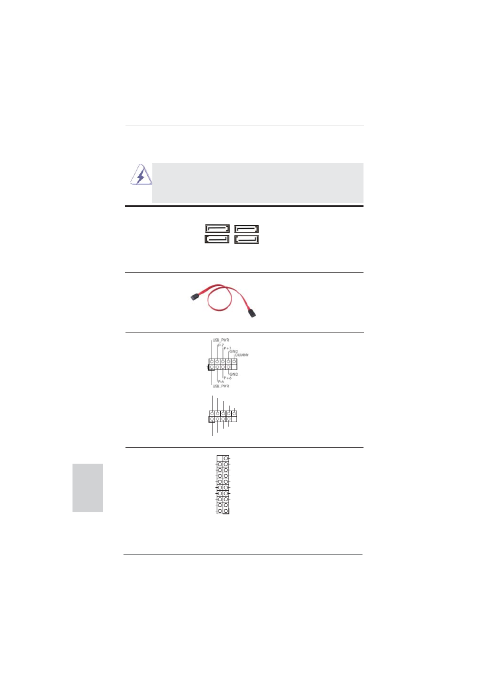
Serial ATA2 Connectors
These four Serial ATA2
(SATA2_0: see p.2, No. 10)
(SATA2) connectors support
(SATA2_1: see p.2, No. 8)
SATA data cables for internal
(SATA2_2: see p.2, No. 12)
storage devices. The current
(SATA2_3: see p.2, No. 11)
SATA2 interface allows up to
3.0 Gb/s data transfer rate.
Serial ATA (SATA)
Either end of the SATA data
Data Cable
cable can be connected to the
(Optional)
SATA / SATA2 hard disk or the
SATA2 connector on this
motherboard.
USB 2.0 Headers
Besides four default USB 2.0
(9-pin USB6_7)
ports on the I/O panel, there
(see p.2 No. 15)
are two USB 2.0 headers on
this motherboard. Each
USB 2.0 header can support
two USB 2.0 ports.
(9-pin USB8_9)
(see p.2 No. 16)
1
USB_PWR
P-8
GND
DUMMY
USB_PWR
P+8
GND
P-9
P+9
SATA2_1
SATA2_0
SATA2_3
SATA2_2
USB 3.0 Header
Besides two default USB 3.0
(19-pin USB3_2_3)
ports on the I/O panel, there is
(see p.2, No. 24)
one USB 3.0 header on this
motherboard. This USB 3.0
header can support two USB 3.0
ports.
IntA_P1_D+
DUMMY
IntA_P1_D-
GND
IntA_P1_SSTX+
GND
IntA_P1_SSTX-
IntA_P1_SSRX+
IntA_P1_SSRX-
Vbus
Vbus
Vbus
IntA_P0_SSRX-
IntA_P0_SSRX+
GND
IntA_P0_SSTX-
IntA_P0_SSTX+
GND
IntA_P0_D-
IntA_P0_D+
1