Reference – ACU-RITE Micro-Line T User Manual
Page 44
MICRO-LINE
Reference Manual
REFERENCE
41
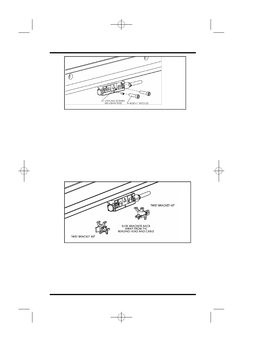
13. Move the axis to align reading head mounting holes.
14. A gap may exist between the reading head and its
mounting surface, requiring leveling screw adjustment.
15. To adjust the leveling screws, place a .001" -.003" feeler
gage (or shim) between one leveling screw and the
mounting surface at a time.
16. Adjust the leveling screw until a slight drag is felt on
the feeler gage. Repeat this for each leveling screw,
3 total.
17. Evenly tighten the two 8-32 SHCS to secure the reading
head.
18. Use Allen wrench to slide brackets away from the reading
head.
19. Remove alignment brackets and save for future use.
20. Route cable with slack loops allowing for axis motion.
21. Secure excess cable by fastening with clips and ties.
22. Move the axis through its full travel. Confirm that the
assembly does not interfere with the machine movement.
MLTmanual.QXD 2/12/02 4:10 PM Page 4