Pc 6415 – Acnodes PC 6415 User Manual
Page 46
14628 Central Blvd,
Chino, CA91710
tel:909.597.7588, fax:909.597.1939
© Copyright 2011 Acnodes, Inc.
All rights reserved. Product descrions
are subject to change without nomation,
please visit Acnodes’ web site at
PC 6415
15” Fanless Pa
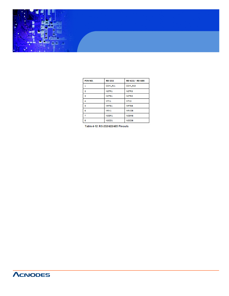
4.11.2.1 RJ-45 Serial Port Pinouts
The pinouts for RS-232, RS-422 and RS-485 communication ar The
COM1 serial port is RS-232 only.
4.11.3 USB Device Connection
There are four external USB 2.0 connectors. All connectors are the PC
Series-N270. To connect a USB 2.0 or USB 1.1 device, p in-
structions below.
Step 1: Locate the USB connectors. The locations of the USB shown
in Chapter 2.
Step 2: Align the connectors. Align the USB device connector onnec-
tors on the bottom panel. See Figure 4-29.
Step 3: Insert the device connector. Once aligned, gently inserte con-
nector into the onboard connector.
4.12 Faceplate Installation
An optional faceplate in a variety of colors is available for mount Series-
N270 frame.
Step 1: Install the faceplate by snapping the faceplate onto the0
frame. See Figure 4-30.