Figure 2.3 rs-232 interface pcb – Xantrex Technology RS232-XPD User Manual
Page 20
Installation and Configuration
Initial Inspection
18
Operating Manual for RS-232 for XPD Series Power Supply
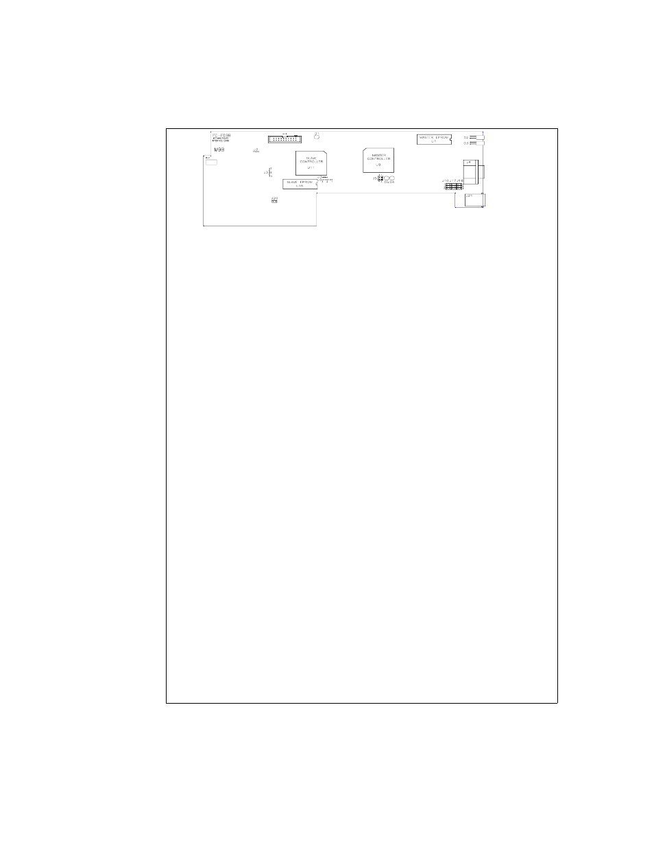
Figure 2.3 RS-232 Interface PCB
JUMPER SELECTION
J2
Local OVP control selection
[closed] [default]. See page 28.
[open] Front Panel OVP Control.
J3
User TTL shutdown (S/D)
selection
[1-2] User TTL S/D line active low. See page 31.
[2-3] [default] User TTL S/D line active high.
J20
Remote OVP Control Selection
[closed] [default]. See page 28.
[open]
J10
RS-232 (J4) transmit and
receive pin selection
[3-1] Receive on pin 3 [default]
[4-6] Transmit on pin 2 [default]
[3-5] Receive on pin 2
[4-2] Transmit on pin 3
J16
RS-232 flow control selection of
RTS/CTS (ready to send/clear
to send) or DTR/DSR (data
terminal ready/data set ready)
[1-3][4-6] [default] RTS input on pin 7 (used with
CTS output on pin 8)
[3-5][4-6] DTR input on pin 4 (used with DSR
output on pin 6)
J17
RS-232 flow control selection of
RTS/CTS or DTR/DSR
[2-4][[3-5] [default] CTS output on pin 8 (used
with RTS input on pin 7)
[2-4][1-3] DSR output on pin 6 (used with DTR
input on pin 4)
Note: All other jumpers are not user-selectable.
LED INDICATORS
D1
Red Diagnostic LED
Bus error or soft restart on Slave circuitry.
D4
Red Diagnostic LED
Soft restart on Master circuitry.
D5
Green Diagnostic LED
Bus error on Master circuitry.
EPROMS
U18
Slave EPROM
See revision number stamped on EPROM.
U1
Master EPROM
See revision number stamped on EPROM.