Xilinx V2.1 User Manual
Page 60
60
Xilinx Development System
Xilinx System Generator v2.1 Reference Guide
The probability of each of the three outcomes depends on the particular Reed-
Solomon code and the nature of the communications channel. The Simulink blocksets
provide excellent capabilities for modeling communication channels and ascertaining
these probabilities.
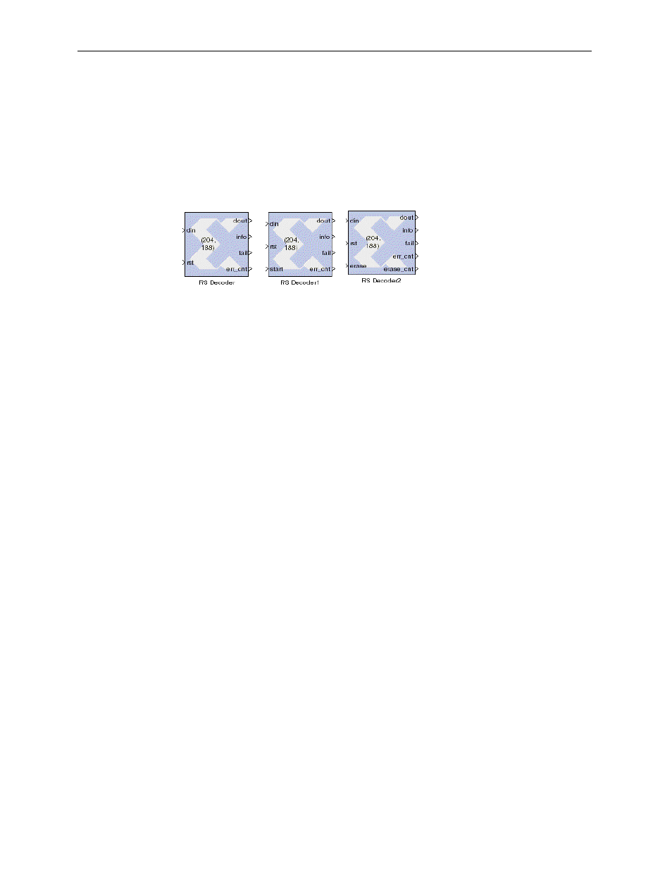
Block Interface
The Xilinx RS Decoder Block has two input (
din, rst
) and four output (
dout,
info, fail, err_cnt
) ports. The RS Decoder block also has two optional input
ports (
start, erase
) and one optional output port (
erase_cnt
).
Figure 3-39: Reed-Solomon Decoder icons, including optional ports
The port descriptions are:
•
din
: carries the codeword to be decoded. The
din
signal must be a
UFixS_0
where S is equal to the symbol width (3 to 12).
•
rst
: carries the reset signal for the decoder. After the
rst
signal is asserted the
decoder initializes the next available input as the first input codeword symbol.
The
rst
signal must be a
UFix1_0
.
•
start
: when start is asserted for a particular sample period, the data on the
din
port is taken as the first input codeword. The start signal is ignored for (n-1)
sample periods after the first start signal is asserted. The decoder always needs
the start signal to be asserted for one sample period to mark the beginning of a
codeword. The start signal must be a
UFix1_0
.
•
erase
: when erase is asserted for a particular sample period, data input on the
din port is marked as an erasure to be corrected by the decoder. The erase signal
must be a
UFix1_0
.
•
dout
: carries the decoded information symbols and the parity symbols of the
input codeword. The
dout
signal must have the same arithmetic type as the
din
input.
•
info
: info output is 1 when there are information symbols on the dout port and 0
when there are parity symbols on the dout port. The info signal is a
UFix1_0
.
•
fail
: supplied when the last symbol of a code block is output on dout. The
decoder sets fail 1 if it determines that there were more errors in the code block
than it could correct. The fail signal is a
UFix1_0
.
•
err_cnt
: supplied when the last symbol of a code block is output on dout. The
err_cnt outputs the number of errors that were corrected by the decoder in the
output code block. The err_cnt signal is a
UFixN_0
(where
N
is equal to the
number of binary bits required to represent n-k).
•
erase_cnt
:
erase_cnt
output is available only when the erasure decoding is
enabled. The
erase_cnt
output is set when the last symbol of a code block is
output on
dout
. The
erase_cnt
output provides a count on the number of
erasures that were flagged for the output code block. The
erase_cnt
signal is a
UFixN_0
(where
N
is equal to the number of binary bits required to represent n).