York SUNLINE PLUS D2EG 048 User Manual
Page 4
The supply and return air duct systems should be designed for the
CFM and static requirements of the job. They should NOT be
sized to match the dimensions of the duct connections on the unit.
CAUTION: When fastening ductwork to the side duct flanges on
the unit, insert the screws through the duct flanges
only. DO NOT insert the screws through the casing.
Outdoor ductwork must be insulated and waterproofed.
Refer to Figure 9 for information concerning side and bottom
supply and return air duct openings.
FILTERS
1" filters are supplied with each unit. 2" replacement filters may
be used with no modification to the filter racks. Filters must
always be installed ahead of the evaporator coil and must be
kept clean or replaced with same size and type. Dirty filters will
reduce the capacity of the unit and will result in frosted coils or
safety shutdown. Minimum filter area and required sizes are
shown in Table 4.
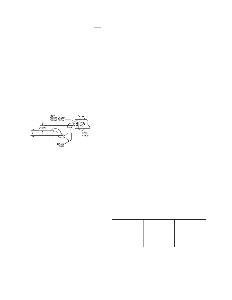
CONDENSATE DRAIN
Plumbing must conform to local codes. Use a sealing compound
on male pipe threads. Install a condensate drain line from the 3/4"
PVC female connection on the unit to spill into an open drain.
NOTE: The condensate drain line MUST be trapped to pro-
vide proper drainage. See Figure 2.
SERVICE ACCESS
Access to all serviceable components is provided by the
following removable panels:
•
Compressor compartment
•
Burner compartment
•
Blower compartment
•
Main control box
•
Filter compartment
•
Motor access (on units with belt-drive option)
Refer to Figure 9 for location of these access panels.
CAUTION: Make sure that all screws are replaced on the unit
to maintain an air-tight seal.
THERMOSTAT
The room thermostat should be located on an inside wall
approximately 56" above the floor where it will not be subject to
drafts, sun exposure, or heat from electrical fixtures or
appliances. Follow manufacturer's instructions enclosed with
thermostat for general installation procedure. Color coded
insulated wires (#18 AWG) should be used to connect
thermostat to unit. See Figure 3 for wiring details.
NOTE: If the unit has an economizer, remove jumper J1 from
terminals 8 and 10 on the relay board to prevent si-
multaneous operation of the compressor and the
economizer. If you want to energize the compressor
for supplemental cooling during the economizer op-
eration, use a thermostat with two stages of cooling.
POWER AND CONTROL WIRING
Field wiring to the unit must conform to provisions of the National
Electrical Code (NEC) ANSI/NFPA No. 70 and/or local
ordinances. The unit must be electrically grounded in
accordance with the NEC (as specified above) and/or local
codes.
Voltage tolerances which must be maintained at the
compressor terminals during start-up and running conditions
are indicated on the unit Rating Plate and Table 1.
The internal wiring harness furnished with this unit is an
integral part of a UL design certified unit. Field alteration to
comply with electrical codes should not be required.
A disconnect switch should be field provided for the unit. The
switch must be separate from all other circuits. Refer to Figure
9 for installation location. If any of the wire supplied with the unit
must be replaced, replacement wire must be of the type shown
on the wiring diagram.
Electrical lines must be sized properly to carry the load. USE
COPPER CONDUCTORS ONLY. Each unit must be wired
with a separate branch circuit fed directly from the meter panel
and properly protected.
CAUTION: When connecting electrical power and control wir-
ing to the unit, waterproof type connectors MUST
BE USED so that water or moisture cannot be
drawn into the unit during normal operation. The
above waterproofing conditions will also apply
when installing a field-supplied disconnect switch.
Refer to Figure 3 for typical field wiring and to the appropriate unit
wiring diagram for control circuit and power wiring information.
BLOWER SPEED SELECTION
Three blower motor speeds are available on the direct-drive
units. The speed selection for the direct-drive units is
determined by the CFM and ESP requirements of the
applications. All units with belt-drive option have an adjustable
motor pulley to achieve the above conditions.
All direct-drive units with 208/230 voltage are shipped with the
wire labeled #116 connected to the “HIGH” speed tap on the
blower motor. If a lower blower motor speed is desired, this wire
should be moved to the “MED” or “LOW” speed tap on the
motor for the speed desired.
All direct-drive units with 460 and 575 voltage are shipped with
the wire labeled #116 connected to the “HIGH” speed tap on
the blower motor. If the medium speed is required, connect
wire #116 to the “MED” speed tap and the blue motor lead to
the “HIGH” speed tap. If the low speed is required, connect wire
#116 to the “LOW” speed tap, the blue motor lead to the “HIGH”
speed tap and the orange motor lead to the “MED” speed tap.
COMPRESSORS
On some units the compressor is mounted on springs which
have been tightened down for shipment only.
After this unit is installed, back out the compressor bolts until
the sleeve clears the top grommet.
CAUTION: Do Not loosen compressor mounting bolts.
COMBUSTION DISCHARGE
The products of combustion are discharged horizontally
through a screened opening on the gas heat access panel.
035-14832-003-A-0204
4
Unitary Products Group
FIG. 2 - RECOMMENDED DRAIN PIPING
Input
Capacity,
(Mbh)
Output
Capacity,
(Mbh)
Available
on
Models
Gas Rate
1
(Ft.
3
/Hr.)
Temp. Rise °F
At Full Input
2
Min.
Max.
50
40
3 Ton
47
15
45
75
60
4 Ton
70
25
55
100
79
3/5 Ton
93
40/25
70/55
125
99
4/5 Ton
116
45/35
75/65
NOTE: Gas Heaters are shipped available for natural gas, but can be converted to L.P. with
Kit Model No. 1NP0434. All furnaces meet the latest California seasonal efficiency
requirements.
1Based on 1075 Btu/Ft
3
.
2The air flow must be adjusted to obtain a temperature rise within the range shown.
TABLE 2 - GAS HEAT APPLICATION DATA