Wayne-Dalton 8800 User Manual
Page 10
10
Please Do Not Return This Product To The Store. Contact your local Wayne-Dalton dealer. To find your local Wayne-Dalton dealer, refer to your
local yellow pages/business listings or go to the
Find a Dealer section online at www.wayne-dalton.com
Tools Needed:
Tools Needed:
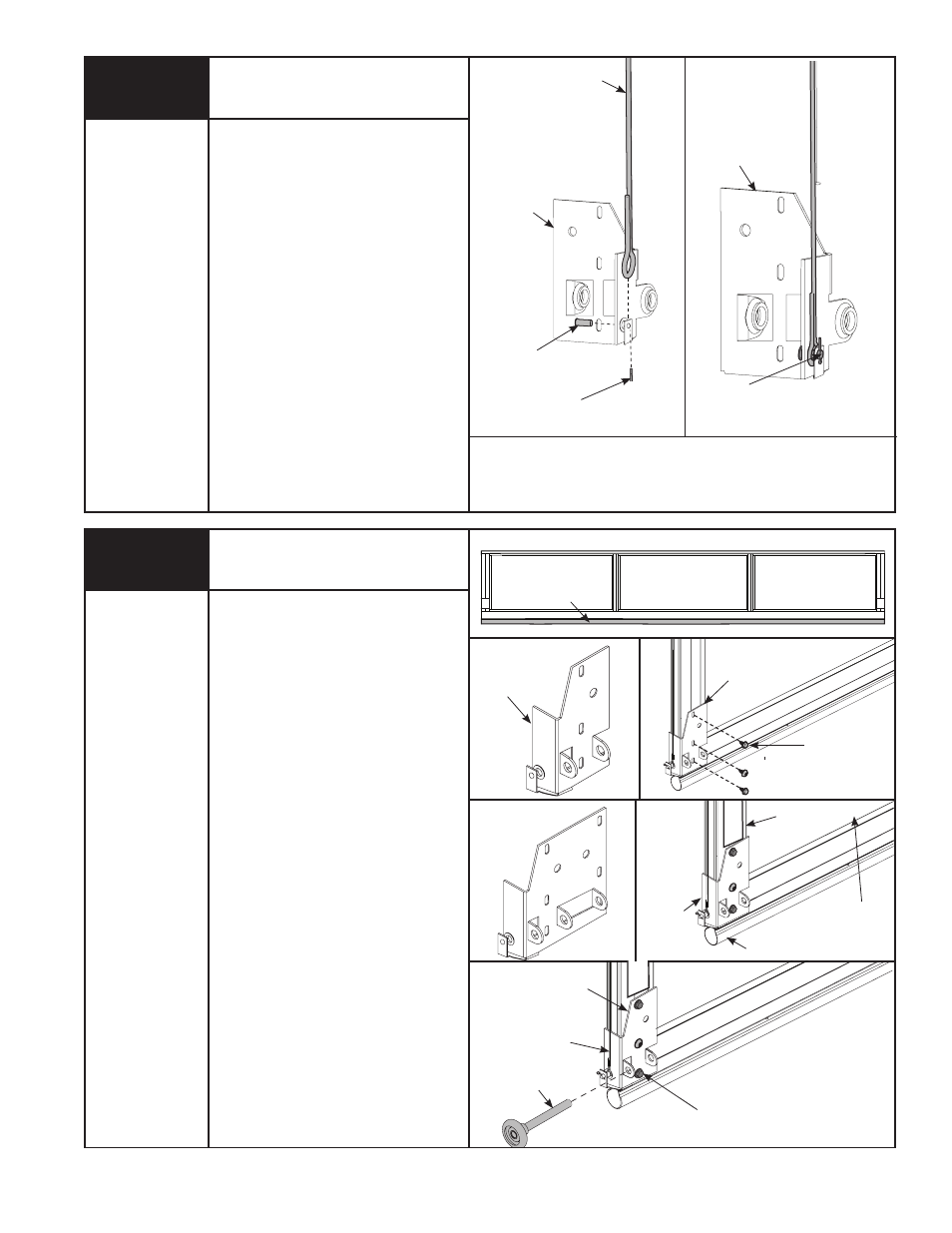
attaching counterbalance cables
to bottom brackets
COUNTERBALANCE
CABLE
CABLE
ATTAChED
BOTTOM
BRACKET
BOTTOM SECTION
ASTRAGAL
Pliers
imPoRTaNT: RIGhT AND LEFT hAND IS
ALWAYS DETERMINED FROM INSIDE ThE
GARAGE LOOKING OUT.
NoTe: For door section identification see page
4.
Locate the right and left hand bottom brackets.
Uncoil the counterbalance cables. Slide the
clevis pin through the left hand bottom bracket
and counterbalance cable. Insert a cotter pin in
the end of the clevis pin, and bend the cotter
pin over to secure.
Repeat for the right hand bottom bracket.
NoTe: Verify astragal (bottom seal) is aligned
with door section. If there is more than 1/2”
excess astragal on either side, trim astragal
even with door section.
NoTe: Specific door models may utilize a dif-
ferent bottom bracket design.
BOTTOM
BRACKET
5
imPoRTaNT: RIGhT AND LEFT hAND IS
ALWAYS DETERMINED FROM INSIDE ThE
GARAGE LOOKING OUT.
NoTe: for door section identification see page 4.
Bottom brackets are right and left hand. Locate
the bottom section; place the left hand bottom
bracket flush against the bottom left hand
corner. Secure the bottom bracket to the sec-
tion using (1) 1/4” x 5/8” tamper resistant self
drilling screw and (2) 1/4” x 7/8” self drilling
screws.
NoTe: Some doors use larger bottom brackets.
Secure these bottom brackets using (1) 1/4”
x 5/8” tamper resistant self drilling screw and
1/4” x 7/8” self drilling screws.
NoTe: All doors are provided with the tamper
resistant fastener for the bottom brackets.
however, the professional installer is most likely
to have the proper tool to install this fastener. If
the homeowner does not have the proper tool to
install the tamper resistant fastener, use a regu-
lar 1/4” x 7/8” self drilling screw in its place.
Insert roller into the roller carrier.
Repeat for right hand side.
6
bottom brackets
BOTTOM
BRACKET
BOTTOM
BRACKET
1/4”- 20 x 7/8”
SELF DRILLING
SCREWS
BOTTOM
BRACKET
BOTTOM
SECTION
Power Drill
7/16” Socket
Driver
WARNING
LABEL
ASTRAGAL
BOTTOM
SECTION
1/4”- 20 x 7/8”
SELF DRILLING
SCREWS
ROLLER
BOTTOM
BRACKET
COUNTERBALANCE
CABLE
CLEVIS
PIN
COTTER PIN