Pre-installation, Installation, Continued) – Wayne CWS50 User Manual
Page 3
3
www.waynepumps.com
Pre-Installation
(Continued)
PACKAGE SYSTEMS
There are four jet pump/tank assemblies
sold as packages (Chart 1).
WELLS
A new well should be pumped clear of
sand before installing the pump. Sand
will damage the pumping parts and
seal. The draw-down level of the well
should not exceed the maximum rated
depth for the pump. The capacity of
the pump will be reduced and a loss of
prime may occur.
Installation
LOCATION
Select a location as close to the water
supply as possible.
Be sure to comply with any state or
local codes regarding the placement
of the pump. The equipment must
be protected from the elements. A
basement or heated pump house is a
good location. Make sure the pump has
proper ventilation. The temperature
surrounding the pump is not to exceed
100° F (40°C) or nuisance tripping of the
motor overload may occur.
This pump is
designed for indoor
installation only. Failure to install indoors
will significantly increase the risk of injury
or death from electrical shock.
PIPING
Piping may be copper, steel, rigid PVC
plastic or flexible polyethylene plastic.
Flexible pipe is not
recommended on
suction pipe (inlet pipe).
The pipe must be clean and free of rust
or scale. Use a pipe joint compound
on the male threads of the metal pipe.
Teflon® tape should be used with
plastic threads. All connections must be
air tight to insure normal operation.
Slope all inlet piping upwards towards
the pump to prevent trapping air.
Unions or hose couplings can be
installed near pump to facilitate removal
for servicing or storage. A rubber hose
installed between the water system and
the house piping will reduce the noise
transmitted to the house.
Plastic pipe can be used on all
installations except 2 in. deep well jet.
The 2 in. deep well jet requires 1-1/4
in. galvanized steel pipe and special
machined couplings (1-13/16 in. O. D.).
The galvanized steel pipe and the
couplings restrict the flow of return
water back to the jet unless the
couplings are machined.
PIPE SIZES
Long horizontal pipe runs and an
abundance of fittings and couplers
decrease water pressure due to friction
loss. See Chart 2 to determine the
proper pipe size.
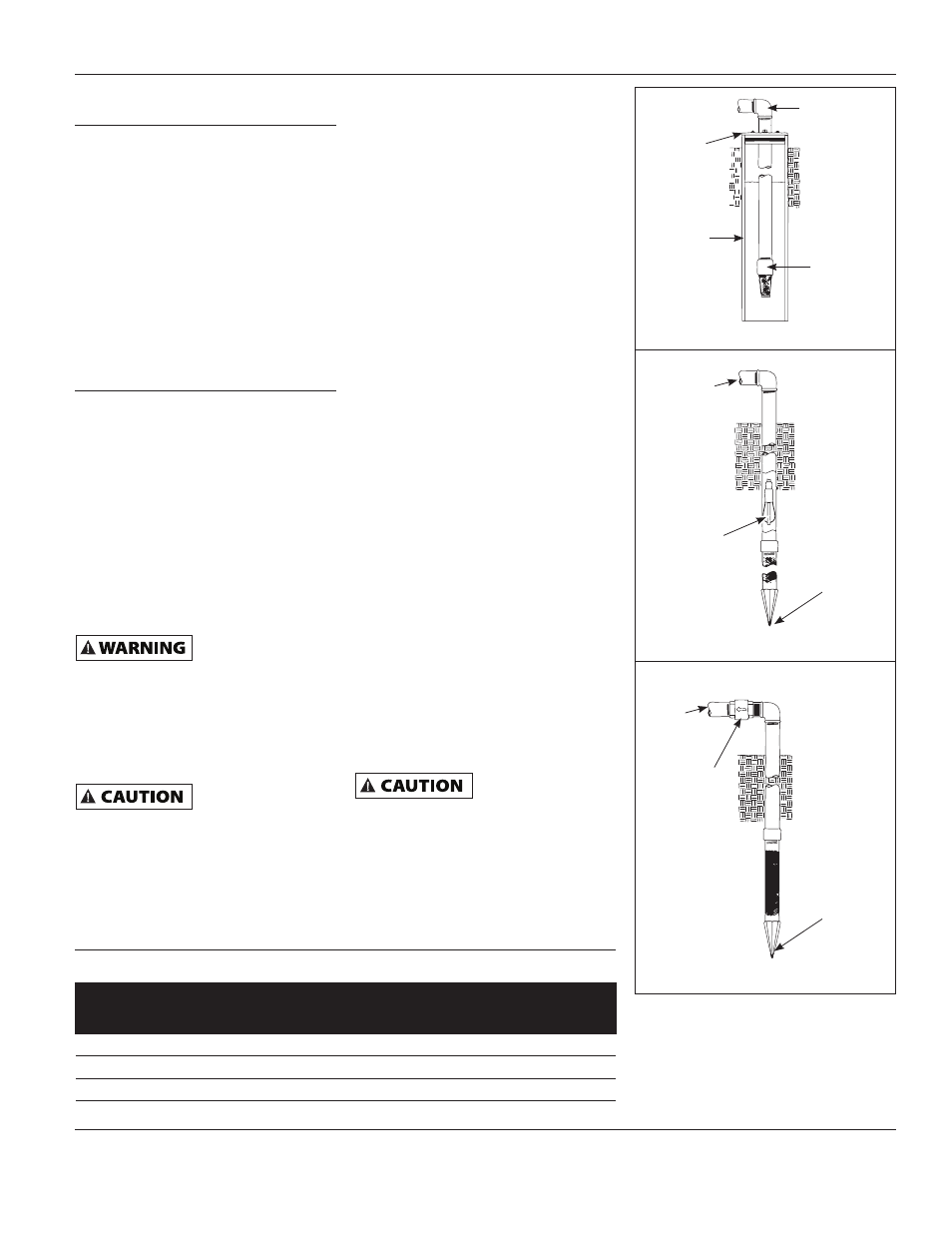
SHALLOW WELL INSTALLATION
A shallow well jet assembly can be used
with the deep well pump when the
pump is located 25 feet vertically of the
water level. Shallow well installations
have only one pipe between the pump
and water supply (Figure 3).
DRILLED WELL (FIGURE 17)
1. Install a foot valve on the first section
of pipe (Figure 3, Illustration A).
2. Lower the pipe into the well.
3. Add pipe until the foot valve is 5
feet below the lowest anticipated
water level.
The foot valve
should be at least 18
in. from the bottom of the well or sand or
sediment could be drawn into the system.
4. After proper depth is reached, install
a well seal or pitless adapter to
support pipe and prevent surface.
water and other contaminants from
entering well.
5. Slope the horizontal pipe upward
toward the pump to eliminate
trapping air. Sloping the pipe will
also aid in priming the pump.
Operating Instructions & Parts Manual
CWS50, CWS75 and CWS100
CHART 1 - JET PUMP/TANK ASSEMBLIES
Type
Air Volume
Control
Required
Well X
Pre-charged
No
PCA
Pre-charged
No
12 P & 30 P Horizontal
Conventional
Yes
FX Horizontal
Pre-charged
No
To Pump
Well
Seal
Foot
Valve
Well
Casing
To
Pump
To
Pump
Drive
Point
Drive
Point
Incline
Check
Valve
Packer
Type Foot
Valve
Illustration A
Illustration C
Illustration B
Figure 3