Unified Brands VENTILATION SYSTEMS User Manual
Page 9
6
4.Terminal Block #2 [TB-2] has three [3] pairs of
terminals and is located at the upper right corner
of the Input/Output Board.
The first pair of
terminals are for the number one wash valve
solenoid. This will be the only wash output
active in a P-10-__ or P-15-__ Control Panel.
The second pair of terminals are for the number
two wash valve solenoid. The third pair of
terminals are for the number three wash valve
solenoid.
5.Terminal Block #3 [TB-3] has three [3] pairs of
terminals. It will not be present on P-10-__ or P-
15-__ Control Panels. The first pair of terminals
are for wash valve solenoid number four. The
second pair of terminals are for the number five
wash valve solenoid. The third pair of terminals
are for the number six wash valve solenoid.
6.Terminal Block #4 [TB-4] has three [3] pairs of
terminals. It will not be present on P-10-__ or P-
15-__ Control Panels. The first pair of terminals
are for the number seven wash valve solenoid.
The second pair of terminals are for the number
eight wash valve solenoid.
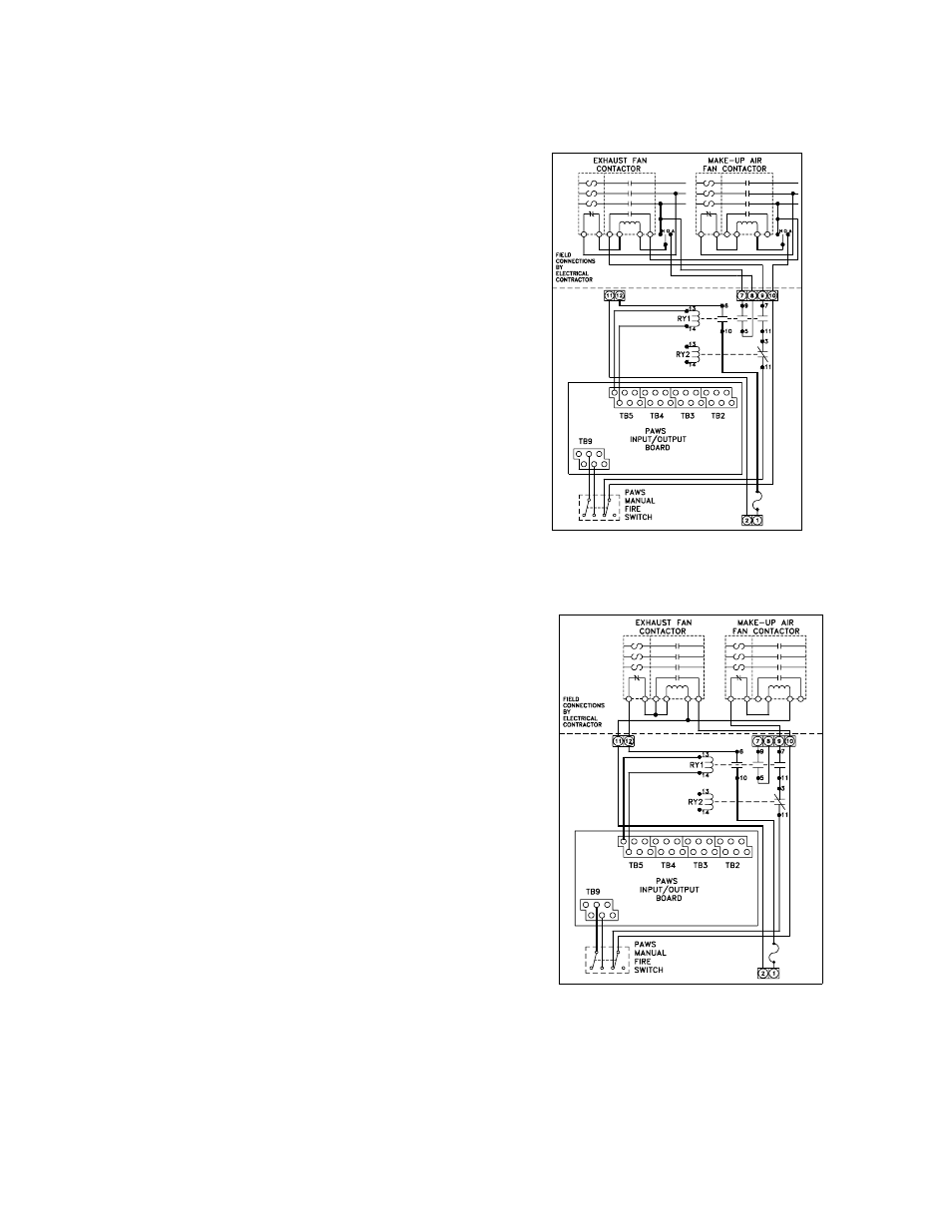
7.Terminal Block #5 [TB-5] has three [3] pairs of
terminals. The first pair provides power for the
detergent pump. The second pair provides
power for the PAWS Alarm/Trouble horn. [The
third pair provides power for the vent fan
contactors. [see figs. #8a & 8b]
Note that the maximum output is one-and-one-
half [1-1/2] amperes. If the total inrush current
for all contactors will exceed this limit, an
intermediate relay must be used.
8.Terminal Block #9 [TB-9] has three [3] pairs of
terminals and is located at the lower left corner of
the Input/Output Board. The first pair of
terminals are for connection to the optional
supervised shut-off valve. If the panel is not
equipped with this option, a jumper wire must be
installed. The second pair of terminals are for
connection to the Manual Fire Switch. The third
pair of terminals are for connection to the
automatic fire switch contacts terminals are for
connection to the automatic fire switch contacts.
Fig 8a
Fig 8b