Unified Brands VENTILATION SYSTEMS User Manual
Page 19
16
h. Fan On During Recovery
The operator can choose to have the fan on
during PAWS recovery periods or remain off.
To have the fan come on during recovery, push
down the right side of switch number one of the
selector switch. To have the fan remain off
during recovery, push down the left side of
switch number one of the selector switch. [see
fig. 19]
i. Power Loss
In the event of a power loss the clock stops but
the PAWS and the Daily Event Schedule are
retained for up to six [6] months.
j. Last Command Indicator
In the Normal Display, the last digit of the top
row indicates the last command put into the
microprocessor.
The letters used are:
L = Power Loss
C = Clock or Program Change
P = Programmed Daily Event
Schedule Command
M = Manual fan or PAWS Command
H = Holiday in progress
LAST
DAY OF AM/PM COMMAND
WEEK TIME INDICATOR INDICATOR
FRI 06:45 PM M
FAN OFF/WASH OFF
PAWS NORMAL DISPLAY
fig. 17B
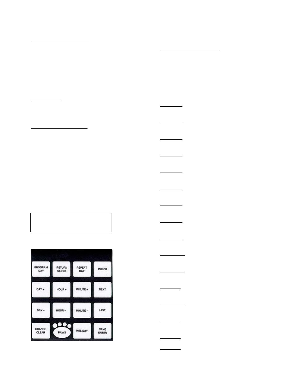
PAWS
Programming Keypad
k. Diagnostic LED Indicators
Because of the use of solid state relay circuits,
a conventional voltmeter may not give reliable
readings as regards to the operation of the
various inputs and outputs. To aid in
troubleshooting, diagnostic LED indicators
have been built into the left-hand side of the
Input/Output Board.
They are shown below.
D-1 Green
Illuminates when the number one wash
output is energized.
D-2 Green
Illuminates when the number two wash
output is energized.
D-3 Green
Illuminates when the number three wash
output is energized.
D-4 Green
Illuminates when the number four wash
output is energized.
D-5 Green
Illuminates when the number five wash
output is energized.
D-6 Green
Illuminates when the number six wash
output is energized.
D-7 Green
Illuminates when the number seven wash
output is energuzed.
D-8 Green
Illuminates when the number eight wash
output is energized.
D-9 Green
Illumintates when the detergent pump
output is energized.
D-10 Green
Illuminates when the PAWS Alarm Horn
output is energized.
D-11 Green
Illuminates when the ventilator fan
output is energized.
D-18 Red
Illuminates when the manual pull station
circuit is in the normal postion.
D-20 Green
Illuminates when the PAWS supervised
valve is open.
D-21 Red
Illumintes when the ventilator automatic fire
detection circuit is activated.
D-32 Red
Glows when the battery circuit is charging.
D-35 Red
Glows when the detergent level is low.