Unified Brands VENTILATION SYSTEMS User Manual
Page 14
11
VI. OPERATION
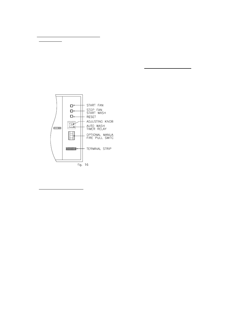
A. VCW Control Panel [Refer to fig. 16]
1.Adjustment
The component layout is shown below. The
only adjustment necessary is for the auto wash
timer relay. Refer to Sec. VII. G, page 18 for
function explanation. Normally three minutes is
used for ovens, steam equipment and light duty
ranges, and five minutes is used for fryers,
griddles, etc. A longer wash may be required
for charbroilers.
2.Sequence Of Operation
Press "START" Button to turn fan[s] ON. When
the time comes to shut down the fan[s] [either
at the end of the day or the end of the cooking
period] press the "STOP" Button. If the system
is equipped with auto wash, the fans will shut
OFF and the auto wash and detergent pump
will come ON. At the end of the Wash Cycle,
the auto wash solenoid closes.
If the fans are OFF you can advance directly to
the Auto Wash [Time-Delay] Period by pressing
the "STOP" Button.
In the event of a fire condition, the fans will shut
OFF [if they were ON] and the Auto Wash will
come ON [if the unit is so equipped]. The unit
will
remain
in
this
condition
until
the
thermoswitch resets itself and then the panel
will return to its mode of operation before the
fire condition occurred.
NOTE: If a fire condition occurs during the
timed auto wash/time-delay period, the timers
will continue to time down. For example, if the
fire were to occur after 5 minutes of a 30
minute time-delay period and lasted for 15
minutes before the fire switch [manual] or
thermoswitch [auto] was activated, then the
fan[s] would come on for 10 minutes, then shut
OFF.
3.Trouble- Shooting [VCW]
a.Fans won't activate when start button is
pushed.
1.Check the wiring to the fan contactor and
verify that it is wired according to the
VCW panel schematic.
2.Check the inter-wiring between the VCW
panel
and
the
electro-mechanical
dampers located on the ventilator hoods.
If the wiring is correct proceed to step c.
3.Check terminals No. 1 and No. 2 with a
voltmeter. 120vac should be present at
all times. If voltage is present, proceed
to step 6.
4.No voltage present. Check wiring to
ensure terminals No. 1 and No. 2 have
been connected to a proper 120vac
power source.
5.Check that all related fuses are intact and
that the circuit breaker in main circuit
breaker panel is "ON".
6.Check
the
fire
switch
pull station
[optional] for proper wiring and also
check that it is properly closed and
latched.
7.Check the dampers on all interconnected
ventilator hoods for a fire condition.
8.In a normal condition damper terminals A
& C will have 120vac. In a fire condition
terminals B & C will have 120vac.
a.If terminals B & C have 120vac fans will
not operate. Voltage present at these
terminals
indicates
that
the
thermoswitches
in the duct have
closed.
These
thermoswitches
automatically reset after cooling to a
temperature below 300
oF.
If the thermoswitch does not reset after
cooling,
replace
it
with
a
new
thermoswitch.
b.Check for 120vac at terminals No. 2 &
No. 5. This voltage should be present
at all times. If voltage is present
proceed to step 8c. If voltage is not
present refer to step 8.a as listed
above.
c.While pushing the "START" Button,
terminals No. 3 and No. 7 will have 120