Unified Brands VENTILATION SYSTEMS User Manual
Page 8
5
IV. ELECTRICAL CONNECTIONS
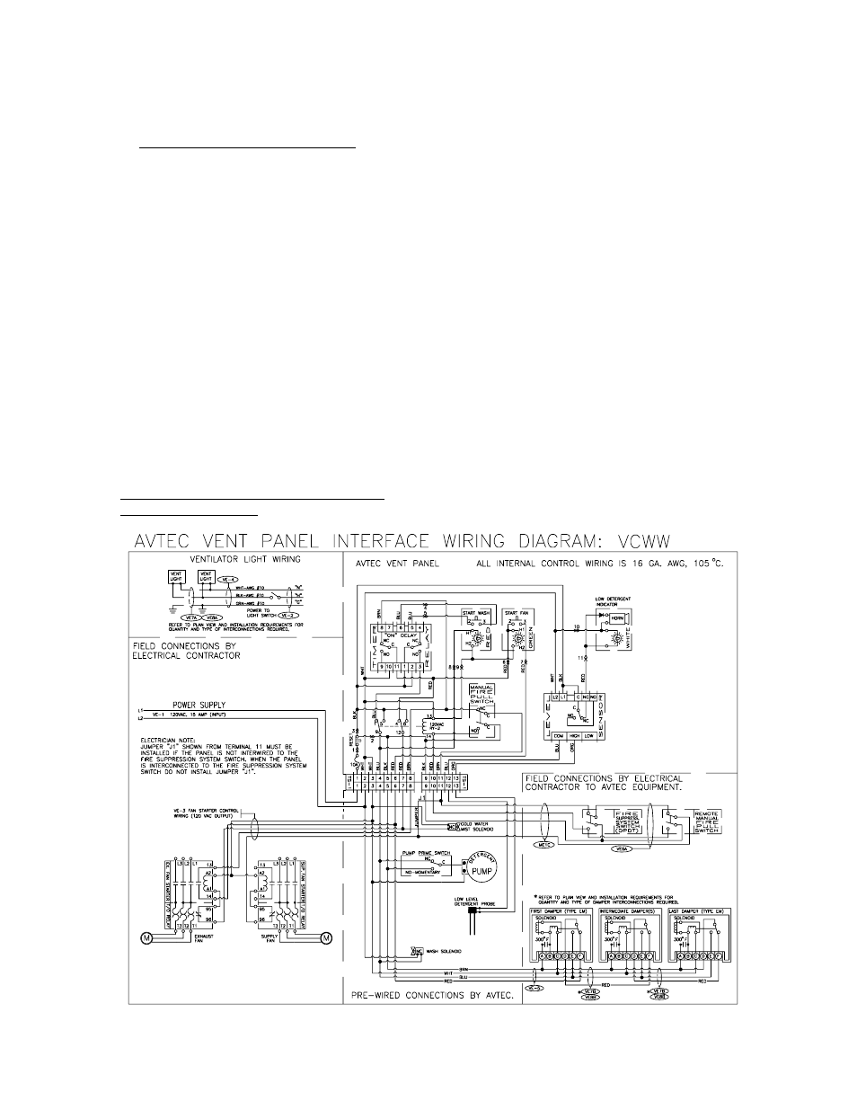
A.VCW Control Panel [Refer to fig. 7]
1.Typical field connection terminals for VCW
Control Panel are shown in fig. 7. For custom
features such as sequential wash, time delay,
etc. refer to AVTEC shop drawing in back of
this manual.
2.Terminals No. 1 and No. 2 are for the
120vac Power Supply. Terminal No. 1 is Hot
and Terminal No. 2 is Neutral.
3.Terminals No. 3 and No. 4 are 120vac
power for the Water Solenoid and Detergent
Pump. These terminals are "hot" whenever
the Water Wash Solenoid and the Detergent
Pump is scheduled to be "ON" or when there
is a fire condition. Terminal No. 5 provides
power for a pump/prime switch with a
momentary closed/normally open contact.
This switch is helpful in checking the
performance of the pump as well as in
priming the pump.
B.Programmable Automatic Wash Sequence
[PAWS] Control Panel
1.Typical Field Connections for the PAWS
Control Panel are shown on [figs. 10, 11, and
12]. Note that all options and connections may
not be included on your system.
2.Terminal Block #1 [TB-1] has three [3]
terminals and is located on the right-hand side of
the Input/Output [I/O] Board. Terminal #1
[uppermost] is for the Hot lead of the power
supply and is protected by a fuse located within
the panel. Terminal #2 [center] is for the Neutral
lead of the power supply. Terminal #3
[lowermost] is used to ground the Input/Output
Board to the Control Panel Housing.
Terminal No. 4 is Hot and Terminals No. 2 & 3
are Neutral.
3.Terminals No. 3 and No. 6 carry 120vac
whenever the fans are scheduled to be ON.
They are used to activate the fan contactor[s]. In
the event of a fire situation, power is removed
from Terminal 5 which provides power for
Terminal No. 6. Terminal No. 6 is the Hot lead
and
Terminal
No.
3
is
Neutral.
7
.
g
i
F