Unified Brands VENTILATION SYSTEMS User Manual
Page 22
19
[Refer to fig. 21]
Grease extractor modules are installed
by sliding the top [narrow] part of the
module into the upper retaining slot and
then lowering the bottom part of the
module into the grease trough slot.
fig. 21
NOTE: Handle faces towards capture area.
2. Grease Receptacles
Grease receptacles are located at each
end of each ventilator section. These
must be cleaned out periodically. The
frequency of this cleaning is dependent
upon the type of equipment used beneath
the ventilator and the duration of its use.
It is suggested that initially the grease
receptacles be emptied daily.
C. Auto Wash Grease Extractors [AW
Models]
These type ventilators have an automatic
wash cycle which requires only occasional
wiping down of inside grease extractor.
1. Grease Extraction Chamber
The front panel is hinged to facilitate
access to the nozzles and grease
extraction baffles.
[Refer to fig.22]
fig. 22
To open, turn all front panel latches
clockwise to the open [unlatched] position
and swing the bottom of the front panel out.
"Kickstands" are provided at each end of the
ventilator section to hold the front panel
open.
2
.
Spray Nozzles
Spray nozzles for hot water wash and
cold water mist are protected from
clogging by wye-strainers located in the
plumbing enclosure. However, scale and
contaminants will accumulate in time and
these will require occasional cleaning to
assure proper wash down and spray
distribution. A paper clip or other pointed
object should be used to scrape
contaminants from the nozzles.
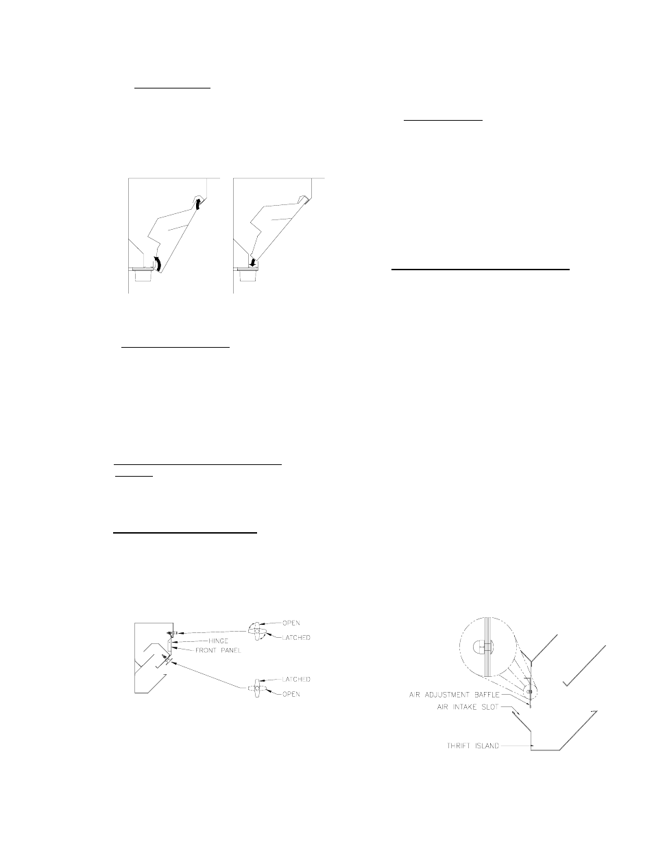
D. Air Adjustment Baffle [Refer to fig. 23]
Some grease extractor models may be
equipped with air adjustment baffles at the
exhaust intake slot. These baffles may be
adjusted to increase or decrease the intake
slot, according to the cfm desired or required
for varying pieces of cooking equipment
underneath. The length of the baffles varies
according to project design specifications and
conditions. The standard opening of nominal 3"
yields approximately 250 cfm/linear ft. and is
used for most cooking appliances. Air flow may
be reduced to a low as 150 cfm/linear ft. for
ovens, steamers, etc. depending on local job
conditions. Adjusting the slot to nominal 1-3/4"
opening will yield approximately 150 cfm/linear
ft.
The Thrift Island Series ventilators uses only
one grease extraction chamber and is designed
for 250-270 cfm/linear ft. on the cooking side
and 150 cfm/linear ft. on the oven/steamer side.
These units are provided with air adjustment
baffles to "fine-tune" the balance of air from
each side, and to change air velocity as job
conditions dictate.
fig. 23