Unified Brands VENTILATION SYSTEMS User Manual
Page 6
3
Fig 4
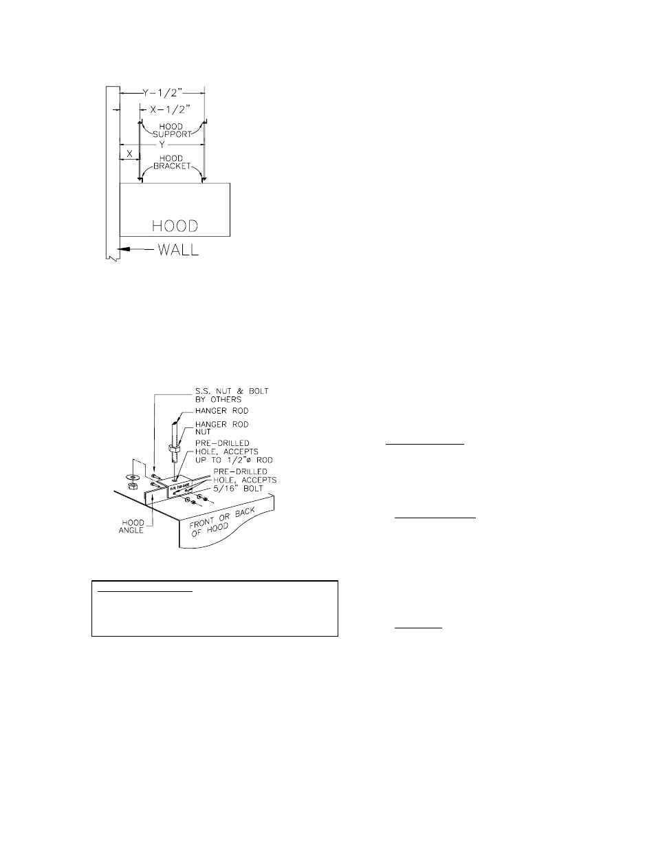
E.The hood should be hung so that the bottom of the
hood is 6'-6" above the finished floor unless otherwise
specified. Carefully lift the hood into position being
certain to avoid scratching the finished surfaces.
Install 1/2" threaded rod from each bracket and the
structural support. Secure rods with heavy duty nuts.
[see fig. #5] Be sure that the hood is level.
Fig 5
Tower Interface Detail
Place trim collar on tower. Position tower under hood.
Fully tighten trim collar retainer hardware after tower
and hood are aligned properly. See fig. A, B, and C
(next page).
F.The entire exhaust duct system must be con-
tinuously welded. This includes the connection
to the duct collar and the roof curb. All welds
must be liquid tight.
NOTE: Welds must not impede operation of
damper.
G.Connect the lights to the circuit breaker panel
through the light switch. All connections should
be in compliance with NFPA 70, National Electric
Code [NEC].
H. Install bulbs in the light fixture[s].
I.Install the grease filters [AF] or modules [AX].
J.Install the grease receptacles [AF or AX]
NOTE: A minimum of a three inch [3"] insulated
fire barrier and air space must be maintained
between the capture area skin of the ventilator
and any combustible surface, including wall and
ceiling. AVTEC ventilators normally have a 3" air
space; insulation is added when specified.
III.CONTROL PANEL [if provided]
Control panels are provided with all auto wash type
ventilators [Models AW- ] and are optional with the
baffle filter type [AF-
] and modular grease
extractor type [AX- ]. Control panels with Models
AF- and AX- do not have the auto wash plumbing
assembly compartments. Any control panel may
be provided with a integral MIST-A- FIRE
Extinguishing System alarm panel and sprinkler
assembly piping; refer to the MIST-A-FIRE
technical manual.
A.Wall Attachment
Control panel dimensions and connection detail
are shown on the enclosed shop drawing.
Panels may be surface mounted, partially
recessed or fully recessed as shown on fig. 6.
1.Surface Mounted
Drill four [4] holes in ventilator plumbing
compartment as required. Be careful not to
damage any components. Avoid drilling into
electrical compartments.
Bolt to wall with
anchor bolts or other acceptable means.
Weight of control panel varies from 90 lbs. to
200 lbs.
2.Recessed
Cut hole in wall 1/2" greater than O/A
dimensions of control box [shown on shop
drawing]. Spacers or support angles may be
necessary to provide proper support.
It is
recommended that panel be bolted to wall
similar to method used for surface mounted
above.