Trane INTELLIPAK ™ ™ ™ ™ ™ Commercial Single-Zone Rooftop Air Conditioners with CV or VAV Control User Manual
Page 98
96
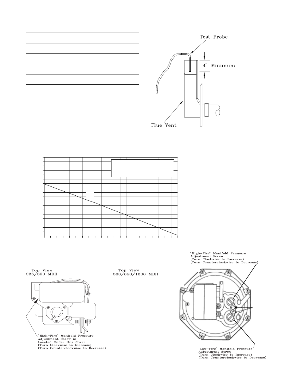
Table 4-8
Natural Gas Combustion Curve
(Ratio of Oxygen to Carbon Dioxide in percent)
0
1
2
3
4
5
6
7
8
9
10
11
12
13
14
15
16
17
18
0 1 2 3 4 5
6 7 8 9 10 11 12 13 14 15 16 17 18 19 20 21
Percent Oxygen
Percent Carbon Dioxide
Curve Fuel
A = 1,000 BTU per cu. ft.
of Natural Gas.
A
Figure 4-8
Gas Valve Adjustment Screw Locations
Table 4-7
Recommended Manifold Pressures and CO
2
Levels
during Furnace Operation (See Notes)
Furnace
MBH
Firing
Manifold
Stage
Rate
%CO2
Pressure
High-Fire
235
100%
8.5-9.5
3.0-3.5
Low-Fire
117
50%
6.0-7.0
0.9
High-Fire
350
100%
8.5-9.5
3.0-3.5
Low-Fire
175
50%
6.0-7.0
0.9
High-Fire
500
100%
8.5-9.5
3.0-3.5
Low-Fire
250
50%
6.0-7.0
1.25
High-Fire
850
100%
8.5-9.5
3.0-3.5
Low-Fire
500
59%
6.0-7.0
1.25
High-Fire
1000
100%
8.5-9.5
3.0-3.5
Low-Fire
500
50%
6.0-7.0
1.25
Manifold pressures are given in inches w.c.
High fire manifold pressure is adjustable on all heaters.
Low fire manifold pressure is non-adjustable on 235 MBH
and 350 MBH heaters.
Figure 4-7
Flue Gas Carbon Dioxide & Oxygen Measurements