Trane INTELLIPAK ™ ™ ™ ™ ™ Commercial Single-Zone Rooftop Air Conditioners with CV or VAV Control User Manual
Page 7
7
Rooftop Module (RTM - 1U48 Standard on all units)
The Rooftop Module (RTM) responds to cooling, heating,
and ventilation requests by energizing the proper unit com-
ponents based on information received from other unit mod-
ules, sensors, remote panels, and customer supplied bi-
nary inputs. It initiates supply fan, exhaust fan, exhaust
damper, inlet guide vane positioning or variable frequency
drive output, and economizer operation based on that in-
formation.
RTM Resistance Input vs Setpoint Temperatures
RTM cooling or
RTM cooling
heating
setpoint input
setpoint input
used as the
Resistance
used as the
source for
(Ohms) Max.
source for a
SUPPLY AIR
Tolerance 5%
ZONE temp
temp setpoint
setpoint (
o
F)
cooling (
o
F)
40
40
1084
45
45
992
50
50
899
55
55
796
60
60
695
65
65
597
70
70
500
75
75
403
80
80
305
n/a
85
208
n/a
90
111
RTM Resistance Value vs System Operating Mode
Resistance
applied to RTM
MODE input
Constant Volume Units
Terminals (Ohms)
Max. Tolerance
Fan
System
5%
Mode
Mode
2320
Auto
Off
4870
Auto
Cool
7680
Auto
Auto
10770
On
Off
13320
On
Cool
16130
On
Auto
19480
Auto
Heat
27930
On
Heat
Compressor Module (SCM & MCM - 1U49 standard on
all units)
The Compressor module, (Single Circuit & Multiple Circuit),
upon receiving a request for mechanical cooling, energizes
the appropriate compressors and condenser fans. It moni-
tors the compressor operation through feedback information
it receives from various protection devices.
Human Interface Module (HI - 1U65 standard on all
units)
The Human Interface module enables the operator to adjust
the operating parameters for the unit using it's 16 key key-
pad. The 2 line, 40 character LCD screen provides status
information for the various unit functions as well as menus
for the operator to set or modify the operating parameters.
Heat Module (1U50 used on heating units)
The Heat module, upon receiving a request for Heating, en-
ergizes the appropriate heating stages or strokes the Modu-
lating Heating valve as required.
Ventilation Override Module (VOM - Optional 1U51)
The Ventilation Override module initiates specified func-
tions such as; space pressurization, exhaust, purge, purge
with duct pressure control, and unit off when any one of the
five (5) binary inputs to the module are activated. The com-
pressors and condenser fans are disabled during the ven-
tilation operation. If more than one ventilation sequence is
activated, the one with the highest priority is initiated.
Interprocessor Communications Board (IPCB -
Optional 1U55 used with the Optional Remote Human
Interface)
The Interprocessor Communication Board expands commu-
nications from the rooftop unit UCM network to a Remote
Human Interface Panel. DIP switch settings on the IPCB
module for this application should be; Switches 1 and 2
"Off", Switch 3 "On".
Trane Communications Interface Module (TCI - Optional
1U54 used on units with Trane ICS
TM
)
The Trane Communication Interface module expands com-
munications from the unit UCM network to a Trane Tracer
100
TM
or a Tracer Summit
TM
system and allows external
setpoint adjustment and monitoring of status and diagnos-
tics. DIP Switch settings on the TCI
module for these applications should be:
Tracer 100 (Comm3): Switches 1, 2, and 3 are "Off";
Tracer Summit (Comm4): Switch 1 is "On", switches 2, and
3 are "Off"
Lontalk Communication Interface Module (LCI - Optional
1U54 - used on units with Trane ICS
TM
or 3rd party Build-
ing AutomationSystems)
The LonTalk Communication Interface module expands
communications from the unit UCM network to a Trane
Tracer Summit
TM
or a 3rd party building automation system,
utilizing LonTalk, and allows external setpoint and configu-
ration adjustment and monitoring of status and diagnostics.
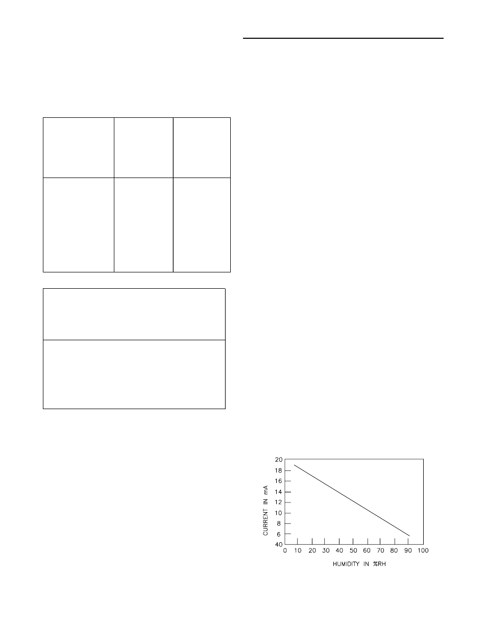
Exhaust/Comparative Enthalpy Module (ECEM -
Optional 1U52 used on units with Statitrac and/or
comparative enthalpy options)
The Exhaust/Comparative Enthalpy module receives infor-
mation from the return air humidity sensor, the outside air
humidity sensor, and the return air temperature sensor to
utilize the lowest possible humidity level when considering
economizer operation. In addition, it receives space pres-
sure information which is used to maintain the space pres-
sure to within the setpoint controlband. Refer to the table
below for the Humidity vs Voltage input values.
General Information (Continued)