Trane INTELLIPAK ™ ™ ™ ™ ™ Commercial Single-Zone Rooftop Air Conditioners with CV or VAV Control User Manual
Page 37
36
Installation (Continued)
12. Position the outlet or discharge port of the steam trap at
least 12" below the outlet connection on the coil(s). This
will provide adequate hydrostatic head pressure to over-
come the trap losses and assure complete condensate
removal.
40 through 130 Ton units;
Utilizes two steam coils stacked together. These two coils
must be piped in a parallel arrangement. The steps listed
below should be used in addition to the previous steps. Fig-
ure 3-13 illustrates the recommended piping configuration
for the steam coils.
13. Install a strainer in each return line before the steam
trap.
14. Trap each steam coil separately as described in steps
10 and 11 to prevent condensate backup in one or both
coils.
15. In order to prevent condensate backup in the piping
header suppling both coil sections, a drain must be in-
stalled utilizing a strainer and a steam trap as illustrated
in Figure 3-13.
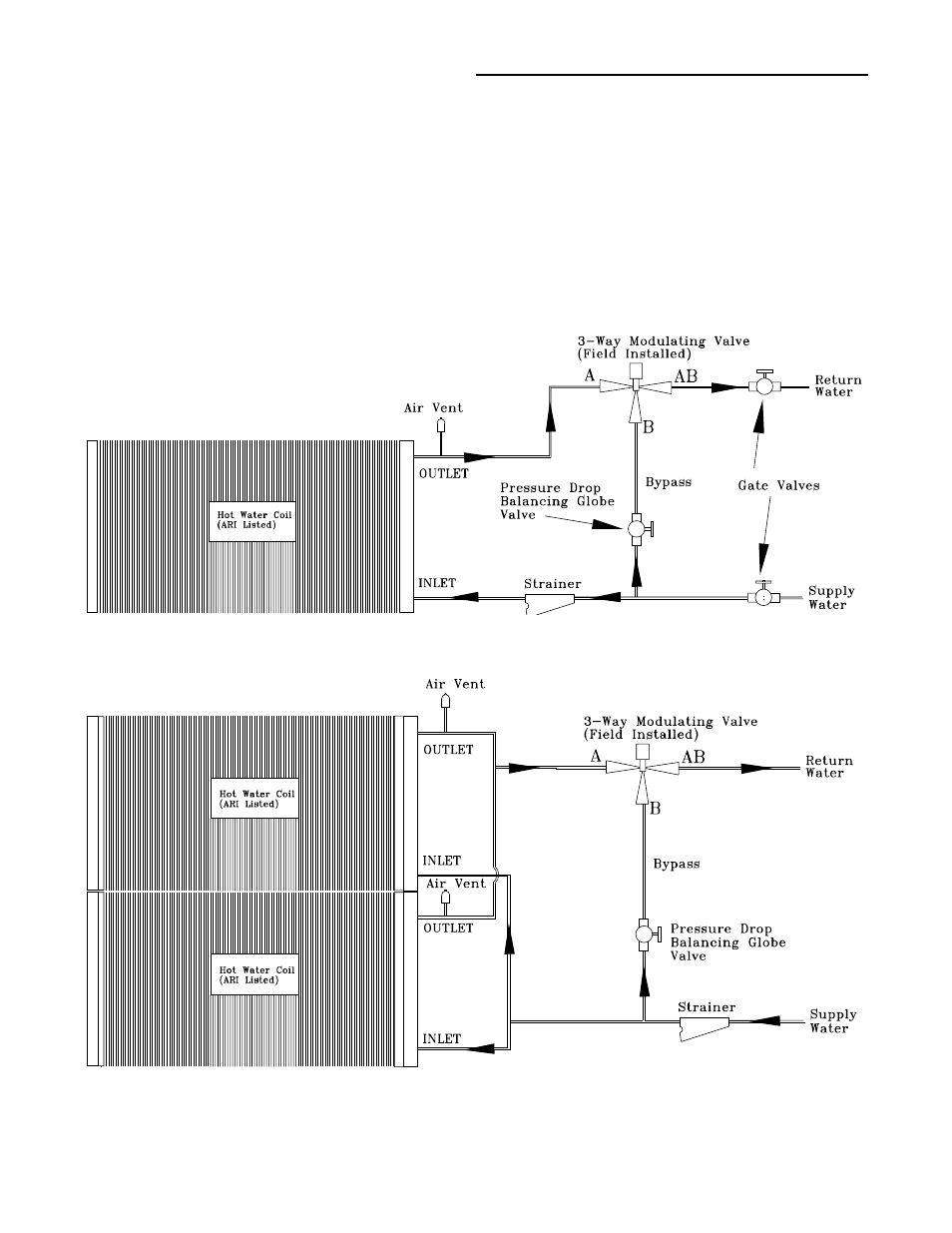
Figure 3-12
Hot Water Piping (20 through 75 Ton)
Hot Water Piping (90 through 130 Ton)