Texas Instruments TMS320DM646X DMSOC User Manual
Page 33
W_STROBE
w
t
WP
(m)
t
cyc
*
1
W_SETUP
)
W_STROBE
w
max
ǒ
t
AW
(m)
t
cyc
,
t
DS
(m)
t
cyc
Ǔ
*
1
W_HOLD
w
max
ǒ
t
WR
(m)
t
cyc
,
t
DH
(m)
t
cyc
Ǔ
*
1
W_SETUP
)
W_STROBE
)
W_HOLD
w
t
WC
(m)
t
cyc
*
3
t
WC
(m)
Strobe
Setup
Hold
t
WR
(m)
t
WP
(m)
t
AW
(m)
t
DS
(m)
t
DH
(m)
EM_CS
EM_A[21:0]
EM_BA[1:0]
EM_WE
EM_D[15:0]
www.ti.com
Use Cases
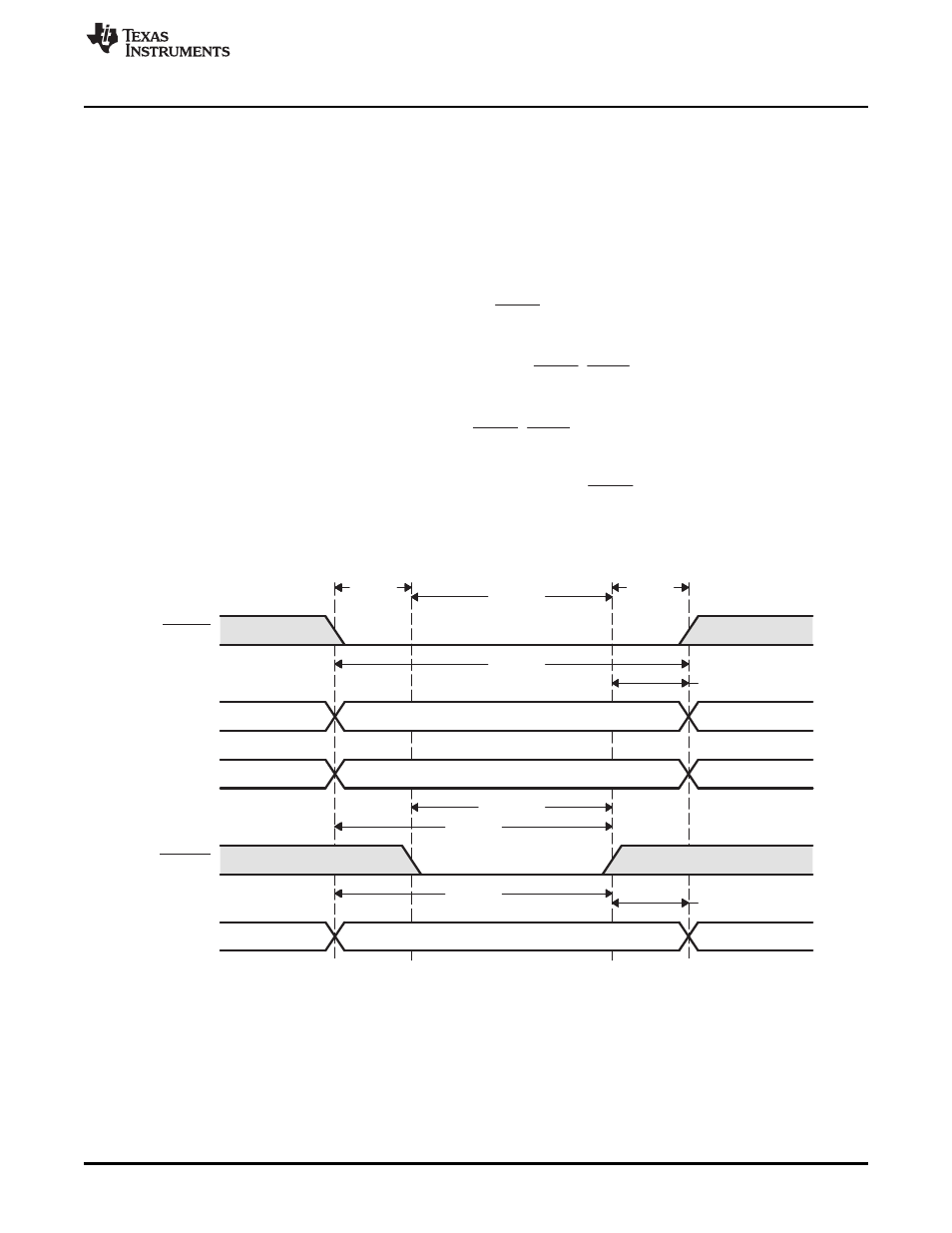
shows an asynchronous write access and describes how the EMIF and ASRAM AC timing
requirements work together to define values for W_SETUP, W_STROBE, and W_HOLD.
From
, the following equations may be derived. t
cyc
is the period at which the EMIF operates. The
W_SETUP, W_STROBE, and W_HOLD fields are programmed in terms of EMIF cycles where as the data
sheet specifications are typically given is nano seconds. This is explains the presence of t
cyc
in the
denominator of the following equations. A minus 1 is included in the equations because each field in
ACFGn is programmed in terms of EMIF clock cycles, minus 1 cycle. For example, W_SETUP is equal to
W_SETUP width in EMIF clock cycles minus 1 cycle.
Figure 13. Timing Waveform of an ASRAM Write
33
SPRUEQ7C – February 2010
Asynchronous External Memory Interface (EMIF)
Copyright © 2010, Texas Instruments Incorporated