Appendix 5 connecting for rs485 communication – Toshiba Tosvert RS485 User Manual
Page 72
E6581315
71
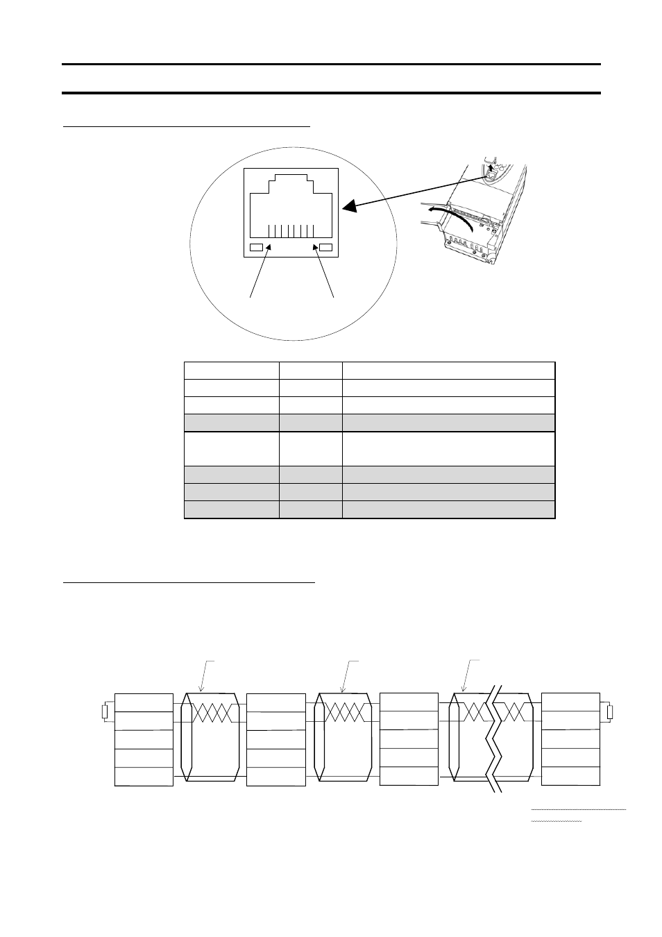
Appendix 5 Connecting for RS485 communication
Connector diagram for 2-wire RS485 communication
Connecting diagram for 2-wire RS485 communication
* Never use pin-7 (P11).
Master
RXD+/TXD+
RXD-/TXD-
SG
CN1
Pin-4
Pin-5
Pin-8
(Pin-3)
Straight
Straight
Terminating resistance
120
-1/2W
Straight
Slave
RXD+/TXD+
RXD-/TXD-
SG
Slave
RXD+/TXD+
RXD-/TXD-
SG
Slave
RXD+/TXD+
RXD-/TXD-
SG
Signal name
Pin number
Description
RXD+/TXD+
4
Same phase reception data (positive line)
RXD-/TXD-
5
Anti-phase reception data (negative line)
FWE
6
FEW (Do not connect the cable.)
SG
8
(3)
Ground line of signal data
PRG(TX)
2
PRG (Do not connect the cable.)
PRG(RX)
1
PRG (Do not connect the cable.)
P11
7
11V (Do not connect the cable.)
Pin-1
Pin-8
This manual is related to the following products: