11 technical data – TechniSat S1 User Manual
Page 65
LNCs are supplied with power by means of the coaxial cable,
to achieve this the receiver supples either 14 or 18 volt power
Interim frequency:
The frequency range broadcast by the satellite cannot be
transmitted via a cable. Therefore the LNC converts the sig-
nal to the interim frequency range of 950 to 2150 MHz. This
makes it possible for the digital receiver to receive and pro-
cess the signal.
1. IF = Interim frequency
11 Technical data
DBS tuner:
Input frequency range
950 .... 2150 MHz
Input level range - 65 dBm ... - 25 dBm
DBS tuner input
F - connector
Input/output impedance
75 Ohms
Output for 1. IF
950 ... 2150 MHz (loop through)
AFC capture range
+/- 3 MHz
Demodulation
Shaped QPSK
Symbol rate
1 ... 45 Mbaud/s, SCPC/ MCPC
FEC
Viterbi and Reed-Solomon
Viterbi rates
1/2, 2/3, 3/4, 5/6, 7/8, automatic
adaptation
Roll-off Factor
35 %
Demultiplexing:
according to ISO 13818-1
Common Interface:
Type
1 Common Interface slot for CI
module
Power requirement
max. 0,3A/5V
PLL modulator:
UHF, Channel 21 ... 69
Antenna input
47 ... 862 MHz
Antenna output
47 ... 862 MHz
Video decoding:
Video compression
MPEG-2 and MPEG-1 compatible
Up to MP@ML (main profile @
main level)
Video standard
PAL / 25 Hz
Active image
720 Pixel x 576 lines
Picture format
4 : 3 / 16 : 9
Picture material 16:9
Automatic adaptation for 16:9 TV
sets (via SCART)
Letterbox filtering for 4:3 TV sets
Audio decoding:
Audio compression
MPEG-1 & MPEG-2 Layer I and II
Audio Mode
Dual (main/sub), Stereo
Sampling frequencies
32 kHz, 44.1 kHz, 48 kHz
Audio parameters:
Output analogue:
Output level L/R 0,5 V r.m.s. (nominal)
65
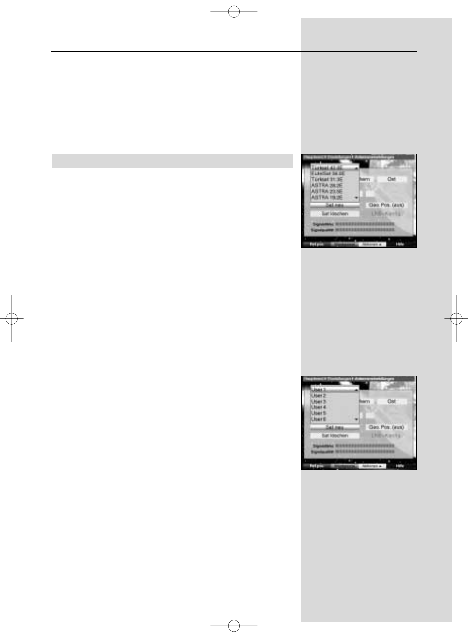
(Fig. 9-11)
(Fig. 9-10)
Bed_anl_.qxd 20.02.04 16:29 Seite 65