Teledyne 4220 User Manual
4220 submerged probe flow meter
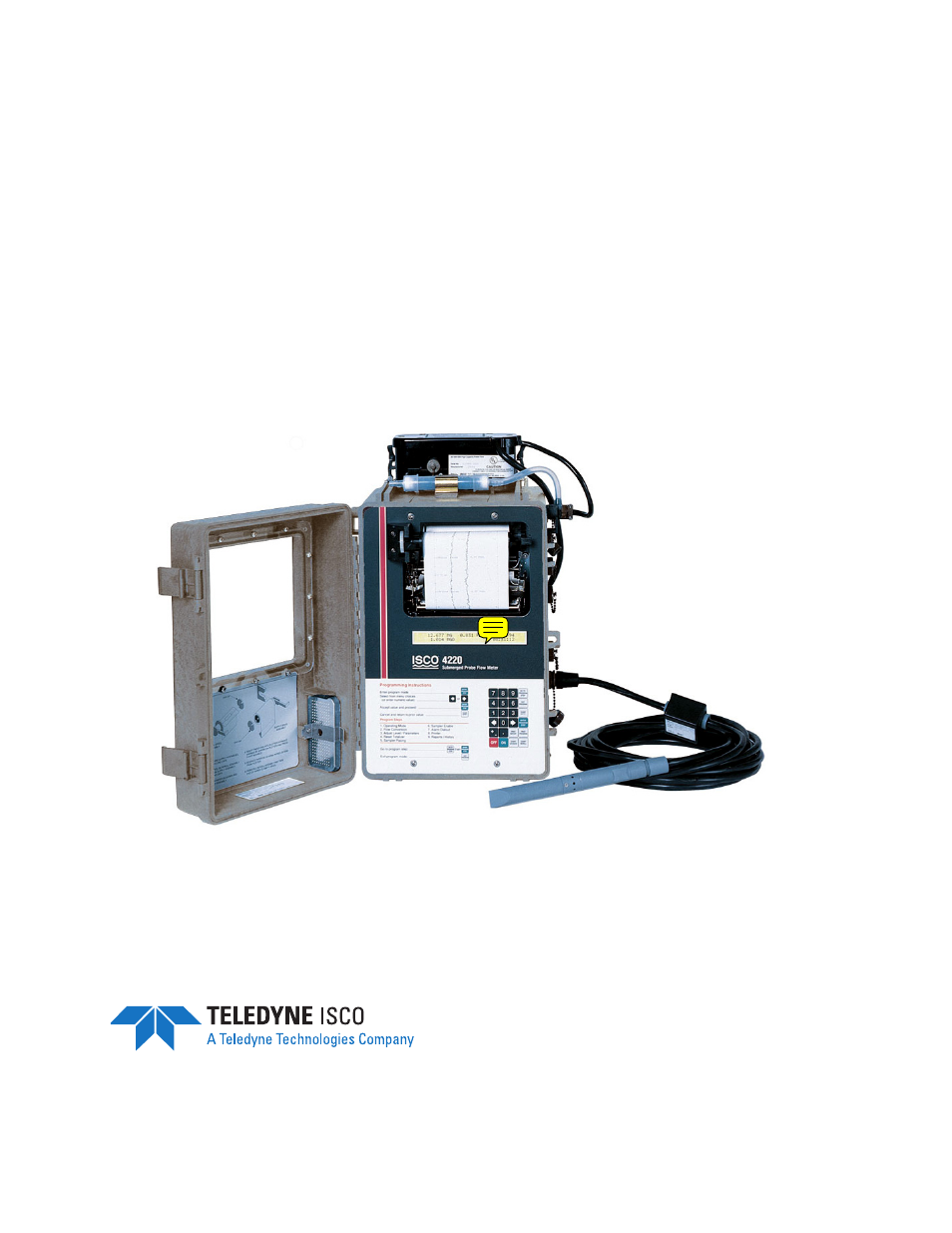
Table of contents
Document Outline
- Foreword
- Safety
- Section 1 Introduction
- Section 2 Programming
- 2.1 Getting Started
- 2.2 Programming Procedure
- 2.3 Description of Program Steps
- 2.4 Interpreting the Program Screens
- 2.4.1 Operating Mode
- 2.4.2 Optional Outputs
- 2.4.3 Step 1 - Program
- 2.4.4 Step 2 - Flow Conversion (Level-to-Flow Rate
- 2.4.5 Step 3 - Parameter to Adjust
- 2.4.6 Step 4 - Reset Totalizer
- 2.4.7 Step 5 - Sampler Pacing
- 2.4.8 Step 6 - Sampler Enable
- 2.4.9 Step 7 - Alarm Dialout Mode
- 2.4.10 Step 8 - Printer
- 2.4.11 Step 9 - Reports/History
- Section 3 Installation
- Section 4 Submerged Probe Installation
- Section 5 Options and Accessories
- 5.1 4200T Modem
- 5.2 Connection to External Serial Device
- 5.3 4-20 mA Analog Outputs: External and Internal
- 5.4 Tipping Bucket Rain Gauge
- 5.5 Isco Flowlink Software
- 5.6 High-Low Alarm Relay Box
- 5.7 Parameter Sensing with Isco 4200 Series Flow Meters
- 5.8 The Temperature Probe
- 5.9 The pH Probe
- 5.10 The Dissolved Oxygen (D.O.) Probe
- 5.11 Installation of Parameter Probes in Mounting Rings
- 5.12 The YSI 600 Multiple Parameter Sonde
- 5.13 Mechanical Totalizer
- Section 6 Maintenance and Service
- Appendix A Replacement Parts
- Appendix B Accessories List
- Appendix C Programming Worksheets
- Appendix D General Safety Procedures
- Appendix E Material Safety Data Sheets
- Index
- Compliance Statements
- Warranty