Figure 11. flow chart dual continuous mode – Texas Instruments TLV1562 User Manual
Page 45
Software Overview
39
Interfacing the TLV1562 Parallel ADC to the TMS320C54x DSP
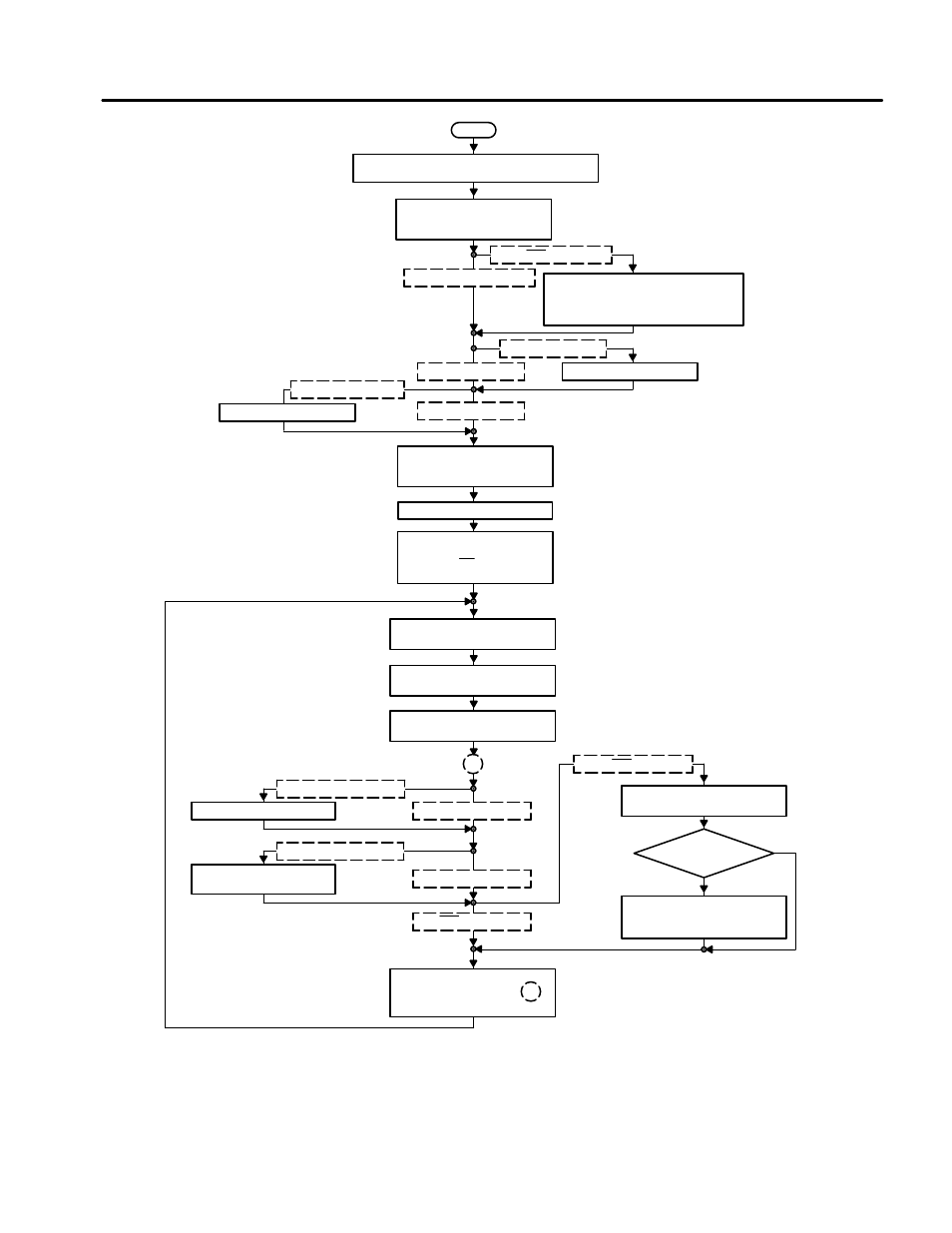
Start
Initialize DSP
Wait States, AR Pointer, IRQ Table, Data Memory, Serial Port
Initialize SPI
Active Transmitter, Use Frame Sync,
Generate External Clock
SAVE_INTO_MEMORY = 1
SAVE_INTO_MEMORY = 0
Initialize DSP Memory For Storing Samples
AR7 Points to The First Store Location
AR0 Points to The Table End
ADCOUNT = Table Size (Number of Samples)
Initialize (Id) The Two ADC Registers
CR0 = CR0_SEND
CR1 = CR1_SEND
IME CALABRATION = 1
Calibrate Internal Midscale Error
IME CALABRATION = 0
SME CALABRATION = 1
Calibrate System Midscale Error
SME CALABRATION = 0
Start Sampling
This Has Been Initialized
by The WR 1/0 Transmit
Wait 450 ns
Table End Reached?
(AR7 = AR0 ?)
Read Sample A
A = Port(ADC)
1
SEND_OUT_PARALLEL = 1
SEND_OUT_PARALLEL = 0
Copy Last Sample to Parallel DAC
SEND_OUT_SERIAL = 1
SEND_OUT_SERIAL = 0
Copy Last Sample to Serial DAC
if Send Register is Empty
SAVE_INTO_MEMORY = 0
SAVE_INTO_MEMORY = 1
Store Sample Into Memory
Save Sample to AR7 – Pointed Location
Ye
s
No
Reset Actual Memory Pointer
AR6/7= First Memory Store Location
AR7= Data_Loc_A; AR6 = Data_LOc_B
Increase I/O-Wait States to 7
Wait 5(6) ADC Clock Cycles
Started at Time Stamp
t
C(RD)
= 800 ns (With 8 MHz ADC Clock)
1
Wait 5(6) ADC Clock Cycles
t
C(RD)
= 800 ns (With 8 MHz ADC Clock)
Read Sample B
B = Port(ADC)
Figure 11. Flow Chart Dual Continuous Mode