Texas Instruments TLV1562 User Manual
Page 35
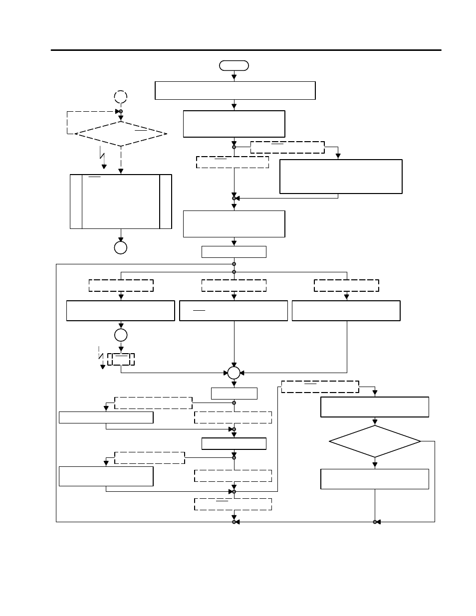
Software Overview
29
Interfacing the TLV1562 Parallel ADC to the TMS320C54x DSP
Table End Reached?
(AR& = AR0 ?)
Start
Initialize DSP
Wait States, AR Pointer, IRQ Table, Data Memory, Serial Port
Initialize SPI
Active Transmitter, Use Frame Sync,
Generate External Clock
SAVE_INTO_MEMORY = 1
SAVE_INTO_MEMORY = 0
Initialize DSP Memory For Sample Store
AR7 Points to The First Store Location
AR0 Points to The Table End
ADCOUNT = Table Size (Number of Samples)
Initialize (Id) The Two ADC Registers
CR0 = CR0_SEND
CR1 = CR1_SEND
Start First Conversion
POLLING_DRIVEN = 1
Wait Until End of Conversion
Poll INTO Pin Until h/0 Transition Occurs
INTO_DRINEN = 1
Main Program
Stay in Idle Mode
NO_INTO_SIGNAL = 1
Wait Until End of Conversion
Wait For a Certain Time
1
INTO
2
Read Sample
SEND_OUT_PARALLEL = 1
SEND_OUT_PARALLEL = 1
Copy Last Sample to Parallel DAC
SEND_OUT_SERIAL = 1
SEND_OUT_SERIAL = 0
Copy Last Sample to Serial DAC
if Send Register is Empty
Start New Conversion
SAVE_INTO_MEMORY = 0
SAVE_INTO_MEMORY = 0
Store Sample Into Memory
Save Sample to AR7 – Pointed Location
H/L Transition on INTO ?
Yes
No
Reset Actual Memory Pointer
AR& = First Memory Store Location
1
No
Yes
INTO (External Interrupt)
Save Modified Register of
The IRQ Routine, if Not
Automatically Saved by The
DSP
(Not Required)
1
Figure 6. Software Flow of the Mono Interrupt Driven Solution