2 rear view – Toshiba KV-HD01A User Manual
Page 12
11
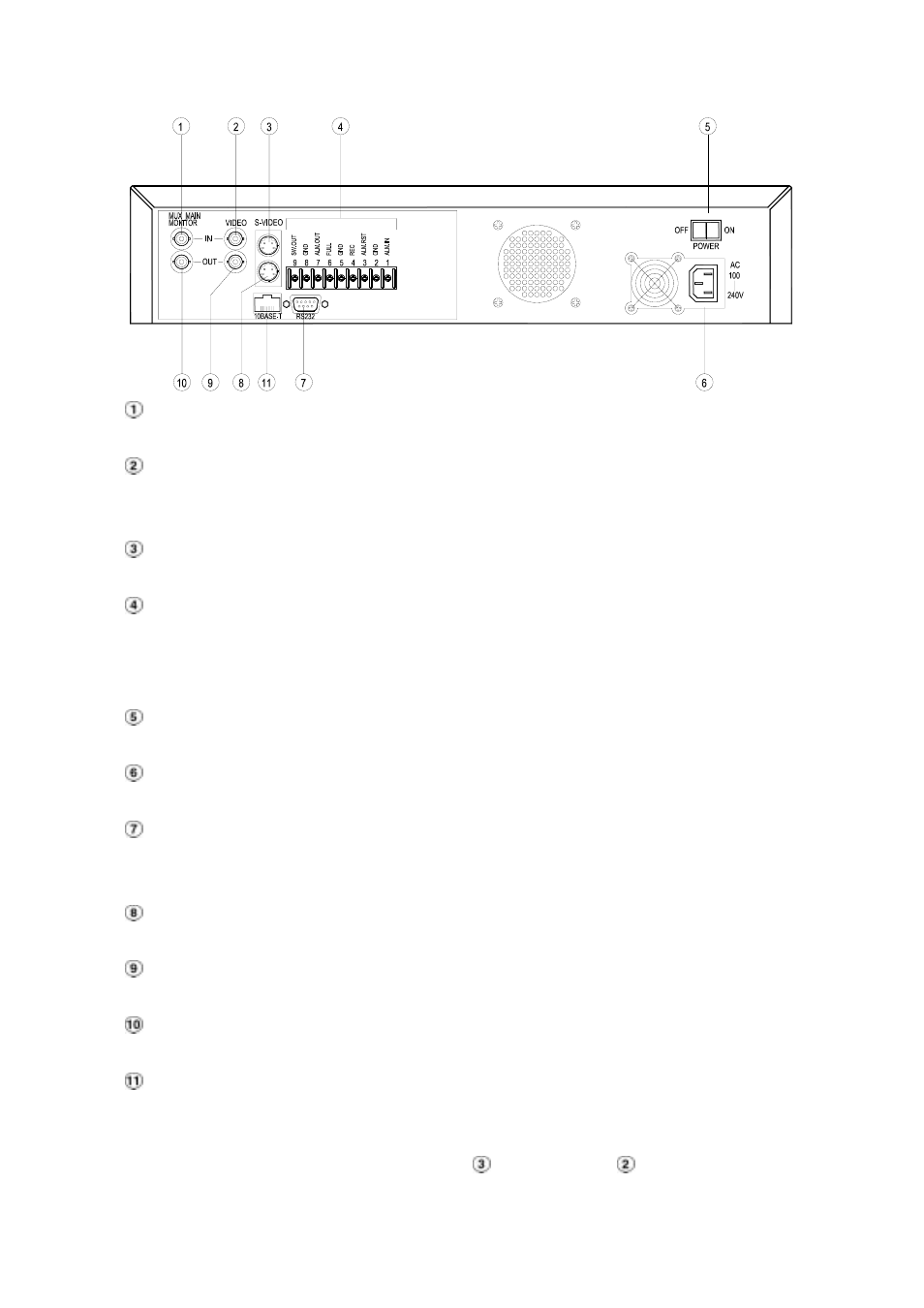
2.2 Rear View
MUX MAIN MONITOR IN Connector:
This BNC connector is used to connect the live video output from a multiplexer to the unit.
VIDEO IN Connector:
This BNC connector is used to connect the video output from a camera or a multiplexer to the
unit.
S-VIDEO IN Connector:
This connector is used to connect the S-video output from a camera or a multiplexer to the unit.
Terminal Block:
There are 9 exposure contacts on this terminal block including SW. Out, GND, ALM. OUT, FULL,
REC, ALM RST, GND, and ALM. IN for connecting with external devices. Please refer to the next
section for details.
Power Switch:
To power the unit on or off.
Plug Outlet:
For connecting with an external power supply.
RS-232 Port:
RS-232 communication port for connecting with an external control device. Please refer to
APPENDIX 1 for more details.
S-VIDEO OUT Connector:
This provides a S-video signal to a multiplexer.
VIDEO OUT Connector:
This provides a composite video signal to a multiplexer.
MONITOR Connector:
This provides a composite video or a multiplexer’s live signal if connected to a display device.
10 BASE-T Connector:
This is a standard RJ-45 connector for 10 Mbps Ethernet networks.
NOTE: The DVR only processes the S-VIDEO IN signal when receiving video signals
simultaneously from both “S-VIDEO IN
” and “VIDEO IN
” connectors.