Loop-control cpu units – Omron Smart Process Control CJ-Series User Manual
Page 8
10
Loop-control CPU Units
Loop-control CPU Units
Loop-control CPU Units
Loop-control CPU Units
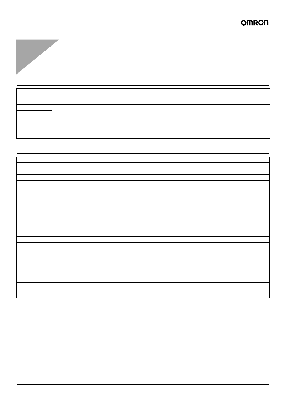
Loop Controller Element Specifications
Model
CPU Unit element
Loop Controller
I/O capacity
Program
capacity
Data memory capacity
Programming
software
Number of
function blocks
Programming
software
CJ1G-CPU45P
1,280 points
(Up to 3 Expansion
Racks)
60 Ksteps
128 K words (DM: 32 K words,
EM: 32 K words
× 3 banks)
CX-Programmer,
CX-Simulator, etc.
300 blocks
CX-Process
CJ1G-CPU45P-
GTC
CJ1G-CPU44P
30 Ksteps
64 K words (DM: 32 K words,
EM: 32 K words
× 1 bank)
CJ1G-CPU43P
960 points (Up to 2
Expansion Racks)
20 Ksteps
CJ1G-CPU42P
10 Ksteps
50 blocks
Item
Specification
Name
Loop-control CPU Unit
Model Number
CJ1G-CPU
@@P(-GTC)
Applicable PLCs
CJ-series PLCs
Area for data
exchange
with CPU Unit
CPU Unit's
Auxiliary Area
• Loop Controller element-to-CPU Unit element:
Run Status Flag, PV Error Input Flag, MV Error Input Flag, Execution Error Flag, Function Block Data-
base (RAM) Error Flag, Automatic Cold Start Execution Flag, Backup during Operation Flag, Function
Block Changed Flag, etc.
• CPU Unit element-to-Loop Controller element:
Start Mode at Power ON: Hot/Cold Start bit.
User allocations in
I/O Memory
User link tables are used to allocate function block ITEM data in any part of I/O memory in the CPU Unit.
(CIO, Work, Holding, or DM Areas, or EM Area bank 0)
Allocations for all
data
HMI function used to allocate function block ITEM data for Control, Operation, External Controller, and
System Common blocks in the specified bank of the EM Area in the CPU Unit.
Settings
None
Indicators
Two LED indicators: RUN and ready
Super capacitor backup data
All function block data (including sequence tables, step ladder program commands), stored error log data
Super capacitor backup time
5 minutes at 25
°C
Data stored in flash memory
Function block data
Backup from RAM to flash memory Executed from CX-Process Tool (as required).
Recovery from flash memory to
RAM
Automatically transferred when power to CPU Unit is turned ON if startup mode is set for a cold start, or
executed from CX-Process Tool (as required).
Influence on CPU Unit cycle time
0.8 ms max. (depends on function block data contents)
Current consumption (supplied
from Power Supply Unit)
1.06 A for 5 VDC (current consumption for Loop-control CPU Unit including CPU Unit element and Loop
Controller element)
Note: Increased by 150 mA when NT-AL001 Link Adapter is used.