Utility software, Face plate auto-builder for ns, Touch panel software – Omron Smart Process Control CJ-Series User Manual
Page 14: Function overview
16
Utility Software
Touch Panel Software
Utility Software
Touch Panel Software
■ Face Plate Auto-Builder for NS
Simply specify the CSV tag file created using the CX-Process Tool to automatically create a project constructed with a Face Plate for Loop-control
CPU Units for use with OMRON's NS-series Programmable Terminals.
Function Overview
• Create windows for monitoring and tuning PID and other function blocks for up to 100 loops (NS System version 4 or higher).
• NS project files for monitoring multiple Loop-control CPU Units from a single NS-series PT can be generated from CX-Process projects for up to
32 multiple nodes.
• When a Segment Program 2 or 3 function block is used for program operation, the Detailed Setting Windows (Time Interval vs. Output Value
Setting Window, Wait Interval Setting Window) used for the parameter settings are also automatically generated.
• NS-Runtime is supported.
Basic Specifications
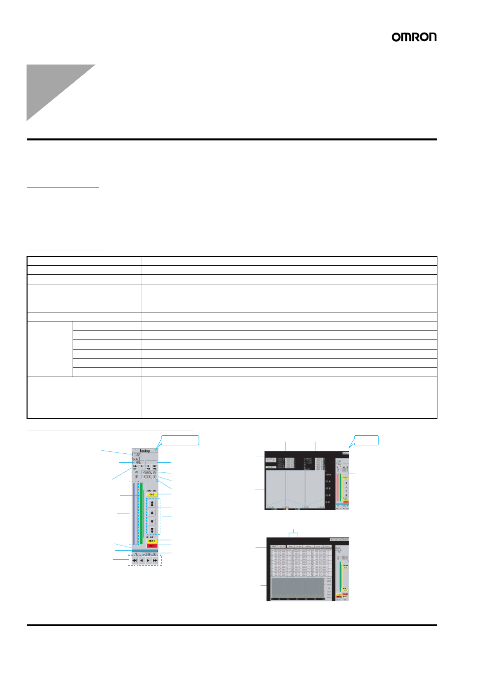
Example of Automatically Created Windows
Item
Specifications
Name
Face Plate Auto-Builder for NS
Model number
WS02-NSFC1-EV3
Applicable PLC products
CJ-series Loop-control CPU Units
CS-series Loop Control Boards (unit version 1.0 or later)
CS-series Loop Control Units (unit version 2.0 or later)
CS1D Process-control CPU Units
Applicable PTs
NS-series NS12, NS10, and NS8 (PT version 2.0 or later), CX-Designer
System
requirements
Computer
IBM PC/AT or compatible
CPU
Celeron 400 MHz or better recommended
OS
Microsoft Windows 98SE, NT4.0 (Service Pack 6a), 2000 (Service Pack 3 or later), or XP
Memory
Recommended: 32 Mbytes min.
Hard disk storage
Recommended: 200 Mbytes free space min.
Monitor
Minimum: 640
× 480 dots
Basic functions
Number of generated loops:100 max., control windows and tuning windows
Applicable face plates: 2-position ON/OFF, 3-position ON/OFF, Basic PID, Advanced PID, Indication and
Operation, Indicator, Segment Program 2 (includes the parameter setting windows),
Segment Program 3 (includes the parameter setting windows)
Number of loops in control windows: 6 loops per window for NS12, 4 loops per window for NS10/NS8
Realtime trend in tuning window: 1-second cycle
Tuning Window
Basic PID Block Screen
Segment program details setting window
MV numerical value
display/input
MAN button/display
AUTO button/display
Time interval,
output value,
and unit for
each step
Setting confirmation
graph (horizontal axis
shows steps)
Up/Down buttons to change SP
SP bar display
CAS button/display
Unit display
SP numerical value display/input
PV numerical value display
Status display 2
(PV error, MV error)
Status display 1
(AUTO, MAN, CAS)
Tag No.
Tag comment
Alarm status
indicators
PV bar display
Alarm set
value display
MV indicator
MV bar display
Up/Down
buttons to change
MV
To Tuning Window
To Control
Window
Write/read setting data
Realtime trend
display
Switch status
Alarm setting
Parameter settings
Function
Block Face
Plate