Important, Switches sw1 (cnv, Switch signal setting description sw4 p8 – Renesas Emulation Pod M306H2T-RPD-E User Manual
Page 33: Sw5 connects the p8, Pin of mcu to the target system. (uses p8, Pin as port p8, Connects the p8, Pin as x, And connect x, And opens x
( 31 / 76 )
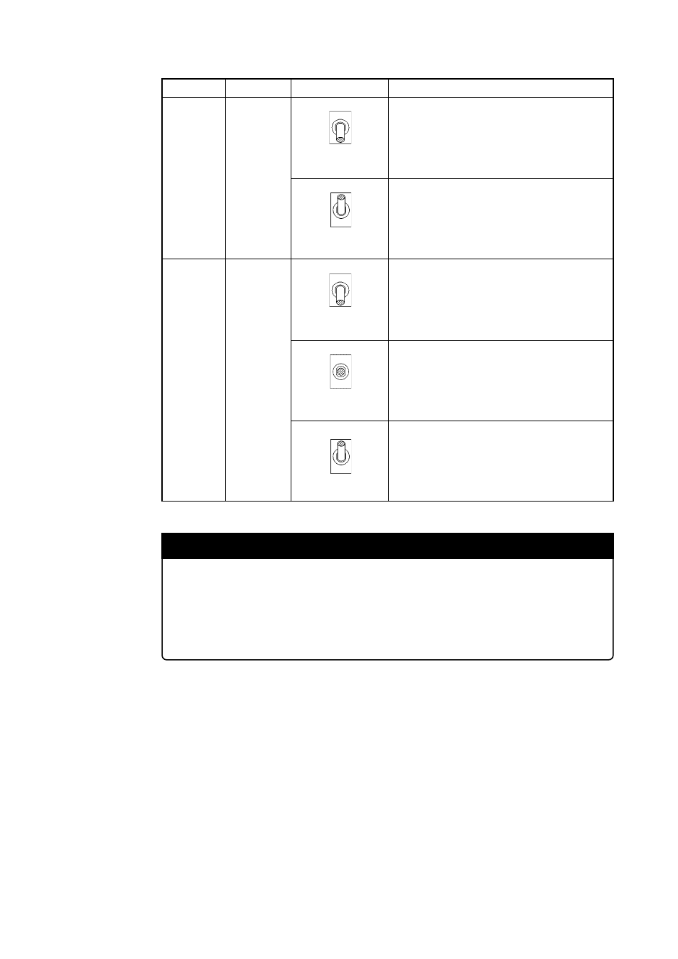
Table 3.2 Switch settings of the M306H2T-RPD-E (2/4)
Switch
Signal
Setting
Description
SW4
P8
7
/X
CIN
P8
6
/X
COUT
SW5
Connects the P8
7
/X
CIN
pin of MCU to the target
system. (Uses P8
7
/X
CIN
pin as port P8
7
)
Connects the P8
6
/X
COUT
pin of MCU to the target
system. (Uses P8
6
/X
COUT
pin as X
COUT
and connect
X
COUT
to the target system)
Connects the P8
6
/X
COUT
pin of MCU to the target
system. (Uses P8
6
/X
COUT
pin as X
COUT
and opens
X
COUT
)
Uses P8
7
/X
CIN
pin as X
CIN
.
Connects the P8
6
/X
COUT
pin of MCU to the target
system. (Uses P8
6
/X
COUT
pin as port P8
6
)
P8
7
X
CIN
SW4
P8
7
/X
CIN
(Factory-setting)
P8
7
X
CIN
SW4
P8
7
/
CIN
P8
6
OPEN
X
COUT
SW5
P8
6
/X
COUT
P8
6
X
COUT
SW5
P8
6
/X
COUT
(Factory-setting)
P8
6
X
COUT
SW5
P8
6
/X
COUT
OPEN
OPEN
IMPORTANT
Note on Switch Settings:
• Switches SW1 (CNV
SS
) and SW2 (BYTE) are used for debugging operation without
connecting the target system. When connecting the target system, set both of them
"OPEN".