10 connecting the external trace/trigger cable – Renesas Compact Emulator M34571T2-CPE User Manual
Page 39
M34571T2-CPE User’s Manual
2. Setup
REJ10J0972-0100 Rev.1.00 February 10, 2006
Page 37 of 72
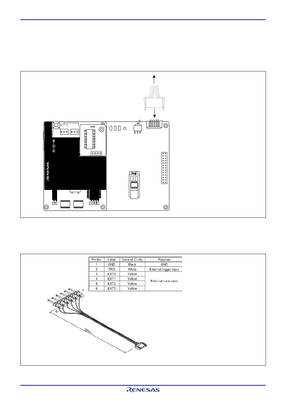
2.10 Connecting the External Trace/Trigger Cable
Using the external trace/trigger cable enables record/reference a hardware break by the external trigger, and changes of an
external signal level in the trace window
2.10.1 Connecting the External Trace/Trigger Cable to the Emulator System
Connect the external trace/trigger cable to the connector J4 of the emulator
Figure 2.15 Connecting the external trace/trigger cable
2.10.2 Connecting the External Trace/Trigger Cable to the User System
Connect the GND, TRG and EXT0 to EXT3 of the external trace cable to the user system. Figure 2.16 shows the pin
assignment of the external trace cable.
Figure 2.16 Pin assignment of the external trace cable
User system
Connect the external cable
to connector J4
M 34571T2-CPEB REV.A
TP
1
VD
D
2
GN
D
TP
2
WR
S
T
PO
F
LE
D
1
PO
W
E
R
SAF
E
ST
A
T
U
S
J4
3V
5V
SW
1
J3
13
14
1
26
MA
DE
PO
W
E
R
C
OMP
ACT
EM
ULATO
R
CL
O
C
K
RE
S
E
T
RU
N
LE
D
3
LE
D
6
L E
D
5L E D
4
PO
W
E
R
SA
FE
LE
D
2
LE
D
1
SA
F
E
PO
W
E
R
PO
W
E
R
CL
O
CK
RE
SE
T
RUN
M
34
571
T2
-C
PE
ST
A
TU
S
SYS
T
E
M
ST
A
T
U
S
TA
RGET
MAD
E
IN
JA
P
A
N
CO
M
P
AC
T
E
M
U
LA
TO
R
POW
E
R
5.
0
V
USB
I
NT
3.
3V
5.
0V
JP 1
JP2
EXT