3 specifications – Renesas Compact Emulator M34571T2-CPE User Manual
Page 20
M34571T2-CPE User’s Manual
1. Outline
REJ10J0972-0100 Rev.1.00 February 10, 2006
Page 18 of 72
1.3 Specifications
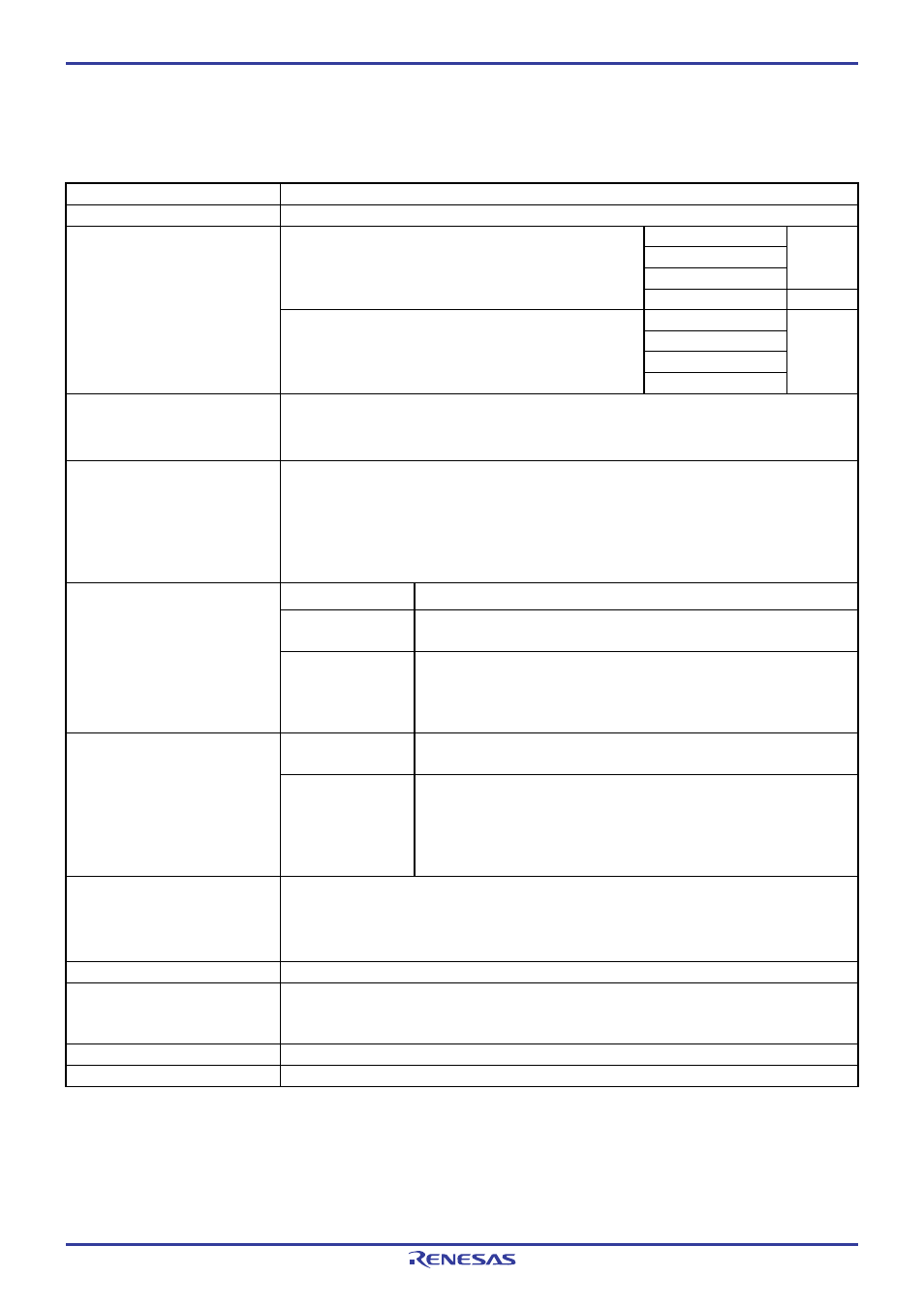
Table 1.6 lists specifications of the M34571T2-CPE.
Table 1.6 M34571T2-CPE specifications
Applicable MCUs
4571 Group
Evaluation MCU
M34571GDFP (mounted in the socket of the emulator)
Divided-by 8-mode
Divided-by 4-mode
Divided-by 2-mode
6.0 MHz
3.0 V
Set the MCU power supply voltage selection switch
(SW1) to 3V.
Through mode
4.4 MHz
Divided-by 8-mode
Divided-by 4-mode
Divided-by 2-mode
Maximum operating frequency
5.0 V
Set the MCU power supply voltage selection switch
(SW1) to 5V.
Through mode
6.0 MHz
Applicable power supply
3.0 V ±5 % or 5.0 V ±5 %
- The power supply can be selected by a switch on the M34571T2-CPEB
- Available only from the emulator, not from the user system
Basic debugging functions
- Download
- Software break (max. 8 points, break after execution)
- Program execution/stop (allows free-run execution supporting software breaks)
- Memory reference/setting
- Register reference/setting
- Disassemble display
Recording cycle
32768 cycles
Trace point
- 2 address points (range/pass count can be set)
- 1 external trigger point
Real-time trace function
Trace mode
- Before Break mode (Records 32768 cycles before program stops)
- Before Trace mode (Records 32768 cycles before event on)
- About Trace mode (Records 32768 cycles before/after event on)
- After Trace mode (Records 32768 cycles after event on)
Hardware break
point
- 2 address points (range/pass count can be set)
- 1 external trigger point
Hardware break function
Break mode
- Address break or trigger break
- Stack over/under flow
- Trace event
- Break at end of trace
- Timer
Time measurement
Time measurement point: 2 address point designation (range can be set)
Resolution: 100 ns
Measurement interval: 8 types
Count source: Emulator timer or MCU cycle
Coverage C0
coverage
Connection to user system
(see “2.8 Connecting the User
System” on page 31)
For 26-pin 2.54-mm-pitch DIP
26-wire normal-pitch cable (included)
Power supply for emulator
DC 5.0 V ±5 %/2 A externally supplied (Prepare a power supply separately.)
Host machine interface
USB (USB 1.1 full-speed, mini-B standard connector)
* Available to connect the host machine that supports USB 2.0. With the USB interface, not all hardware (such as host
machine, USB devices, USB hub) combination will work and guaranteed.