2004 roberts-gordon – Roberts Gorden Vantage TF-Series User Manual
Page 36
ROBERTS GORDON
®
T F-S
E RIE S
S
U BMI TT AL
S
HEE T
© 2004 Roberts-Gordon
APPLI CAT IONS, ENGIN EE RING AND DE TAI LE D GUIDANCE ON SYST EMS DE SI GN, I NSTALL ATION AND PRODUCT PE RFORMANCE I S AVAIL ABL E UPO N REQUE ST. ROBERTS GO RDON
®
PRODUCTS ARE TO BE
INSTAL LE D ONLY I N ACCOR DANCE WIT H L OCAL L AW S, CODES AND RE GULAT IONS, AND ONLY BY A CONTRACTO R QUALI FIE D IN THE INST AL LAT ION AND SE RVICE OF GAS-F IRE D HEAT ING E QUIPMEN T.
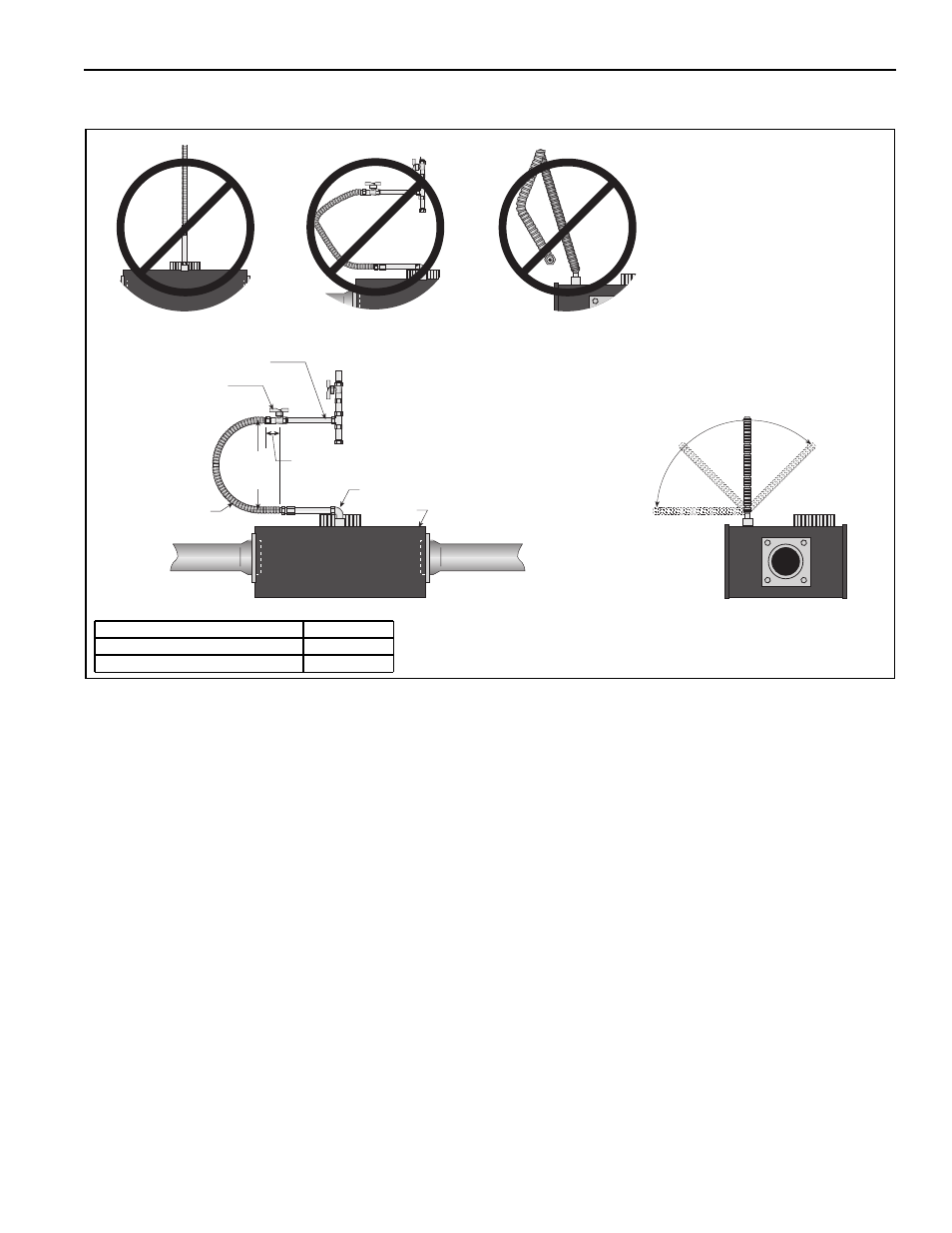
GAS PIPING
FIGURE 1: Gas Connection with Stainless Steel Flex Connector
Hold gas nipple securely
with pipe wrench when
attaching the flex gas
connector.
Failure to follow these
instructions can result in
product damage.
Burner
2" (5 cm)
Stainless
Steel Flex
Gas Connector
Shut-Off Valve
(included
with connector)
3/4" NPT Pipe
Shut-Off Valve must be parallel to
burner gas inlet. The 2" (5 cm)
displacement shown is for the cold
condition. This displacement may
reduce when the system is fired.
12"
(30 cm)
45°
90°
0°
45°
90° Pipe Elbow (not supplied)
Descri ption
Part Number
1/2” Flex G as Line
91412200
3/4” Flex G as Line
91412203