Roberts Gorden Vantage TF-Series User Manual
Page 11
ROBERTS GOR DON
®
T F-S
E RIE S
S
UB MI TT AL
S
HEE T
© 2004 Roberts-Gordon
APPL ICATION S, ENGI NEE RING AND DET AI LE D GUID ANCE ON SYST EMS DE SIGN, INSTAL LATI ON AND PRODUCT PE RFORMANCE IS AVAI LABLE UPON RE QUEST. ROBERT S GORDON
®
PRODUCT S ARE T O BE
INSTAL LE D ONL Y IN ACCORDANCE WI TH L OCAL L AWS, CODES AND REGUL AT IONS, AND ONLY BY A CONT RACT OR QUALI FIE D I N THE I NST ALL AT ION AND SE RVICE OF GAS-FIRE D HE AT ING EQUI PME NT.
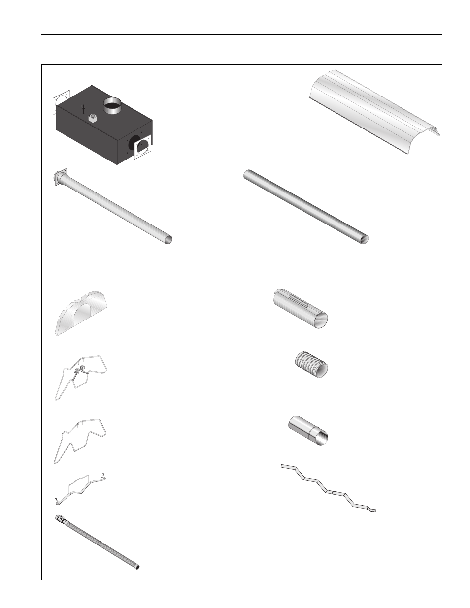
TF-SERIES ASSEMBLY OVERVIEW
Major Component Descriptions
Burner with Tube Gasket
Must be installed with the
flame observation
window facing down.
Reflector
(Aluminum or
Stainless
Steel)
Alternate overlap as
shown on overview and
on Page 10, Figure .
Minimum overlap is 7” (18 cm).
Tube and Reflector Hanger
with Clamp Package
Position this hanger no more
than 4” (10 cm) away from
the burner.
Coupling Assembly
with Lock
Reflector End Cap
Punch out center
section to
accommodate heat
exchanger tube.
Tube and Reflector Hanger
Suspend system from these
hangers.
Flex Gas Line with
Shut Off Cock
Tube
Hot Rolled or Heat
Treated Aluminized Tube
Supplied in 10’ (3 m) lengths.
Burner Tube
Supplied in 10
'
(3 m) lengths. Burner
tube is always the first tube
after the burner.
Reflector Support Strap &
Wire Form
Turbulator
Turbulator must be
installed in the last standard
section of tube. Turbulator is
not required on the TF-250/
300/350/380. For installation
see Page 15, Section .
Flexible Boot
Flexible boot is used to
connect the last tube to
the vent.
Vent Sleeve
Vent Sleeve installed
inside flexible boot.