9 can interface, Figure 2.10 interface with a can-mounted system – Renesas 32185 User Manual
Page 57
32185/32186/32192/32195/32196 Group
Starter Kit User’s Manual M3A-2154G52B
REJ10B0223-0150/Rev.1.50
Mar 2008
Page 49 of 80
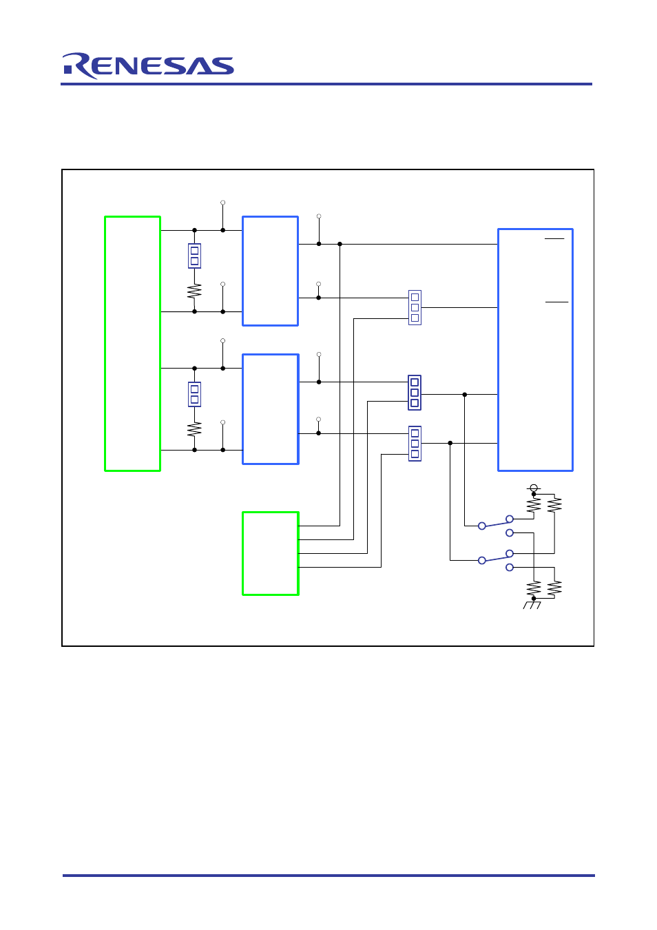
2.9 CAN
Interface
The evaluation board is interfaced to a CAN-mounted system by using the internal CAN functions
of the M32R/ECU.
CON1
FX1-144S-1.27DS
CN3
TM2REA-1208
2
3
1
2
J14
3
1
TX7
CANH
CANL
TXD
RXD
U4
PCA82C250T
TX10
R14
TX11
CANH
CANL
U5
PCA82C250T
TX15
R17
J11
J9
TX8
TX9
TX12
TX13
TXD
RXD
J16
3
1
2
P220
P221
P137
P136
CANH1
CANL1
CANH2
CANL2
J17
S6
P220/CTX0/HACK
P221/CRX0/HREQ
P137/TIN23/CTX1
P136/TIN22/CRX1
U1
M32R/ECU
S7
2
2
VCCE
3
1
3
1
* CNx,CONx : Connector
* Jx : Jumper
* Rx : Resister
* Sx : Switch
* TXx : Test pin
* Ux : IC
Note: TX7, TX8, TX9, TX10, TX11, TX12, TX13 and TX15 are not mounted but they only have patterns available.
Figure 2.10 Interface with a CAN-mounted System