4 specifications of the evaluation board – Renesas 32185 User Manual
Page 45
32185/32186/32192/32195/32196 Group
Starter Kit User’s Manual M3A-2154G52B
REJ10B0223-0150/Rev.1.50
Mar 2008
Page 37 of 80
1.4 Specifications
of the Evaluation Board
1.4.1 Electrical
Characteristics
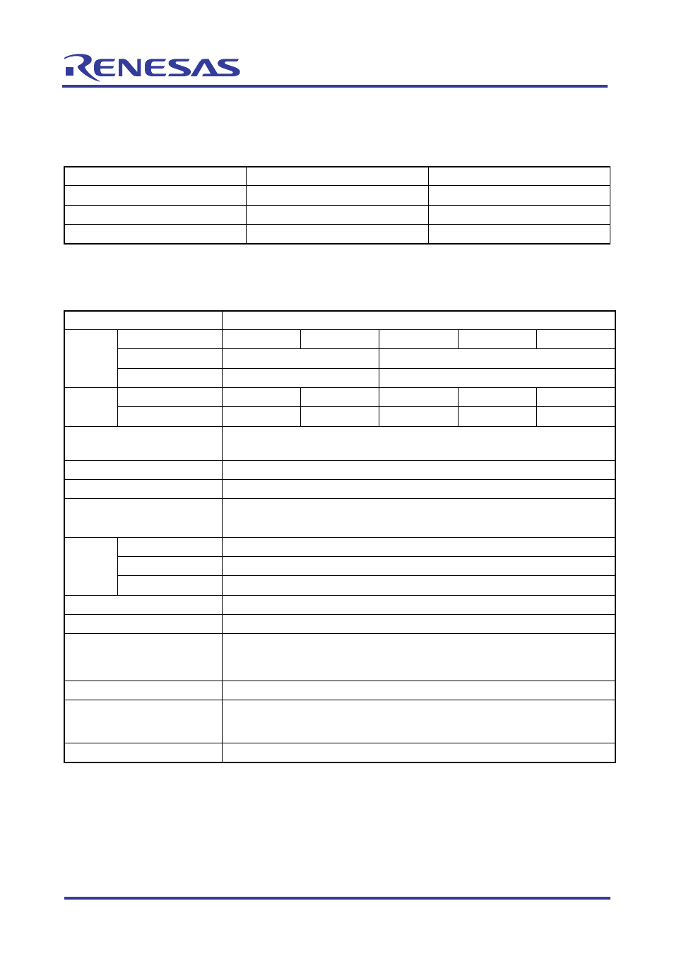
Table 1.3 Electrical Characteristics
Symbol Parameter
Rated
Value
VCCE,VCC-BUS
Power supply voltage
4.75 V to 5.25 V
Tstr
Storage ambient temperature
0°C to 60°C
Topr
Operating ambient temperature
5°C to 35°C
Note: Operating conditions require that no dewdrops and corrosive gas be present.
1.4.2 Functional
Characteristics
Table 1.4 Functional Characteristics
Item M3A-2154G02A
Group
MCU
name
32185 32186 32192 32195 32196
Clock input
10MHz
20MHz
CPU
CPU clock
80MHz
160MHz
Flash memory
512KB
1MB
1MB
512KB
1MB
Memory
SRAM 32KB
64KB
176KB
32KB
64KB
RS-232C interface
Comes standard with a 9-pin Dsub connector (CN5) for serial
communication with the host PC (Windows)
JTAG interface
Comes standard with a 10-pin JTAG connector for Renesas SDI (XCN1)
NBD interface
Comes standard with a 14-pin NBD connector (CN4)
CAN interface
Comes standard with a 2-channel connector for CAN communication (CN3),
a CAN-to-Dsub connector (9-pin) conversion cord included
VCCE
Power supply, Connector (CN2)
VCC-BUS
Power supply for bus control pin, Connector (CN1)
Power
supply
LED
Illuminates in red when powered on (LED1)
General-purpose output
LED indicators (L0–L7), CPU ports (P110–P117)
General-purpose input
Toggle switches (S0–S7), CPU ports (P130–P137)
Reset
Reset switch (SW1), reset input (red pushbutton)
*Please be careful to configure a reset circuit according to your
system.
Serial I/O
Rotary switch (SW2), which selects one of four serial I/O channels
Analog input
VR controls (VOL0, VOL1)
Connects these VR controls with AD0IN0 and AD0IN1 to use them to
control inputs on ports
Extension
Extension connectors (CON1, CON2)