3 mod select circuit – Renesas 32185 User Manual
Page 49
32185/32186/32192/32195/32196 Group
Starter Kit User’s Manual M3A-2154G52B
REJ10B0223-0150/Rev.1.50
Mar 2008
Page 41 of 80
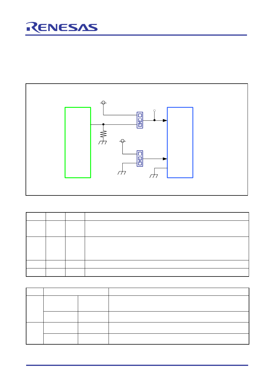
2.3 MOD Select Circuit
This circuit is used to set operation modes of the M32R/ECU. The MOD0 power supply is
configured in such a way that MOD0 is switched from the EXTMOD0 signal of extension connector
(CON2) by using a jumper (J8).
The MOD1 power supply defaults to 0 V. The MOD2 power supply is fixed to 0 V.
J2
U1
M32R/ECU
MOD1
3
1
2
VCCE
J8
TX6
3
1
2
VCCE
EXTMOD0
MOD0
MOD2
CON2
FX1-144S-1.27DS
* CONx : Connector
* Jx : Jumper
* TXx : Test pin
* Ux : IC
Note: TX6 is not mounted but it only has one pattern available.
Figure 2.3 MOD Select Circuit
Table 2.3 Operation Mode Settings
MOD0 MOD1 MOD2
Description
0 0 0
• When flash reprogramming is disabled: Single-chip mode
• When flash reprogramming is enabled: Flash rewrite + single-chip mode
1 0 0
• When flash reprogramming is disabled: Processor mode
• When flash reprogramming is enabled: Flash rewrite from boot ROM +
single-chip mode
0
1
0
External extension mode
1 1 0
Settings
inhibited
Table 2.4 MOD Select Circuit (Jumper)
Name Condition
Description
Shorted
between 1–2
Default
Controls MOD0 by EXTMOD0, unless control MOD0 by
EXTMOD0 sets MOD0 to 0
J8
Shorted
between 2–3
Sets MOD0 to 1
Shorted
between 1–2
Default
Sets MOD1 to 0
J2
Shorted
between 2–3
Sets MOD1 to 1
Note: The J2 and J8 jumpers are shorted by pattern wiring on the reverse side of printed circuit board.
Case of setting the condition except for default, setting the jumper is required after cutting the pattern
for default condition by referring to the chapter 3.8 Setting jumper by cutting