1 emissivity setting (analog controlled), Installation, 24 mi – RayTek MI Miniature Infrared Sensor User Manual
Page 32
Installation
24
MI
5.4.1 Emissivity Setting (analog controlled)
The input FTC1 can be configured to accept an analog voltage signal
(0 to 5 VDC) to provide real time emissivity setting. The following
table shows the relationship between input voltage and emissivity.
U in V
0.0 0.5 … 4.5 5.0
Emissivity
0.1 0.2 … 1.0 1.1
Table 4: Ratio between Analog Input Voltage and Emissivity
Example:
The process requires the setting of emissivity:
• for product 1: 0.90
• for product 2: 0.40
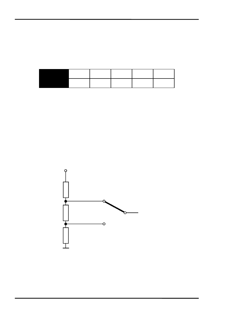
Following the scheme below, the operator needs only to switch to
position “product 1” or “product 2”.
Figure 14: Adjustment of Emissivity at Input FTC1 (Example)
“product 1”
“product 2”
4.0 V (ε=0.9)
1.5 V (ε=0.4)
To the input FTC1
of the sensor
R1 = 200 Ω
R2 = 500 Ω
R3 = 300 Ω
+ 5 VDC