Installation, Installation checklist, Locating your gas stove – Regency P33-NG3 User Manual
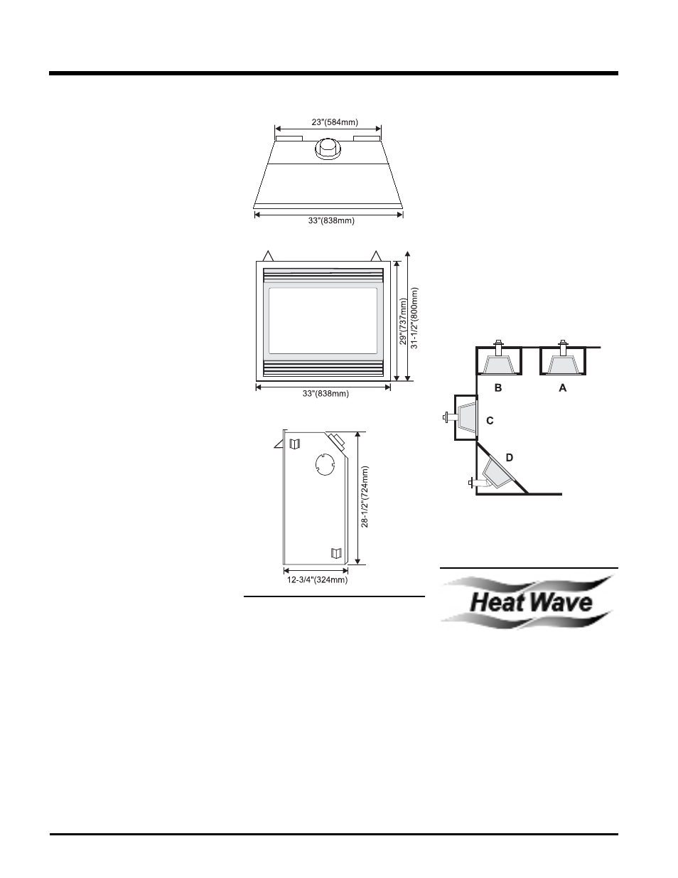
Page 6: Unit dimensions
Regency P33-3 Zero Clearance Direct Vent Gas Fireplace
INSTALLATION
CHECKLIST
1) Locate appliance
a) Room location, page 6
b) Clearances to Combustibles, page 7
c) Mantle Clearances, page 7
d) Framing & Finishing Requirements,
page
8
e) Venting Requirements, pages 10 to
15.
2) Assemble Top Facing Support and Side
Nailing Strips, page 9. (NOTE: must be
done before installing unit into fi replace.)
3) Install vent, pages 10 to 24.
4) Make gas and electrical connections. Test
the pilot. Must be as per diagram. Page 25.
Convert to Propane if desired, page 26.
5) Install brick panels (optional), page 27.
6) Install logs and embers and rockwool where
indicated on page 27.
7) Install Flush Door Front (Standard) and
optional Flush Gold Trim, page 28.
8) Install optional Double Screen Door, page
29.
9) Install Optional Bay Front and optional Bay
Gold Trim, page 29.
10) Install Louvers (Flush or Bay), pages 28
and 29.
11) Install optional Wall Switch, Remote Control,
or Wall Thermostat, page 33.
11) Install Optional Fan, page 35.
13) Final check.
Before leaving this unit with the customer, the
installer must ensure that the appliance is fi r-
ing correctly and operation fully explained
to customer.
This includes:
1) Clocking the appliance to ensure the correct
fi ring rate (rate noted on label) after burning
appliance for 15 minutes.
2) If required, adjusting the primary air to ensure
that the fl ame does not carbon. First allow
the unit to burn for 15-20 min. to stabilize.
CAUTION: Any alteration to the product that
causes sooting or carboning that results
in damage is not the responsibility of the
manufacturer.
Diagram 1
INSTALLATION
LOCATING YOUR
GAS STOVE
1) When selecting a location for your stove,
ensure that the clearances outlined on this
page are met.
2) Provide adequate clearances for servic-
ing.
3) The appliance must be installed on a fl at,
solid, continuous surface (e.g. wood, metal,
concrete). This may be the fl oor, or raised up
on a platform to enhance its visual impact.
If the appliance is going to be installed on
carpeting, combustible linoleum tile or other
combustible material other than wood fl oor-
ing, the appliance must be installed on a
metal or wood panel extending the full width
and depth of the appliance.
UNIT DIMENSIONS
4) The P33-3 can be installed in a recessed
position or framed out into the room as in
A, B, C, D. See Diagram 1.
5) This appliance is Listed for bedroom instal-
lations when used with a Listed Millivolt
Thermostat. Some areas may have further
requirements, check local codes before
installation.
6) The P33-3 Direct Vent Gas Fireplace is ap-
proved for alcove installations, which meet
the clearances listed on this page.
7) We recommend that you plan your instal-
lation on paper using exact measurements
for clearances and fl oor protection before
actually installing this appliance. Have a
qualifi ed inspector, dealer, or installer review
your plans before installation.
Note: For vent terminations see page 10.
A)
Flat on Wall
B)
Flat on Wall Corner
C) Recessed
into
Wall/Alcove
DUCT SYSTEM
OPTION
KIT #946-556
The HeatWave Air Duct Kit increases the ef-
fectiveness of your fi replace by dispersing warm
air from the fi replace to remote locations in the
same room or other rooms in your home.
Up to two kits may be installed on the fi replace.
Please Note: Only 1 HeatWave kit may be
operated at one time. This includes the internal
blower option as well.