2 elbow package configuration, Step 7.2.1 elbow installation, Step 7.2.2 elbow installation – Roberts Gorden Low Intensity Unitary Heater Designed for Harsh Environments HE-40 User Manual
Page 35: Step 7.2.3 reflector joint installation
SECTION 7: O
PTIONAL
H
EATER
A
CCESSORIES
29
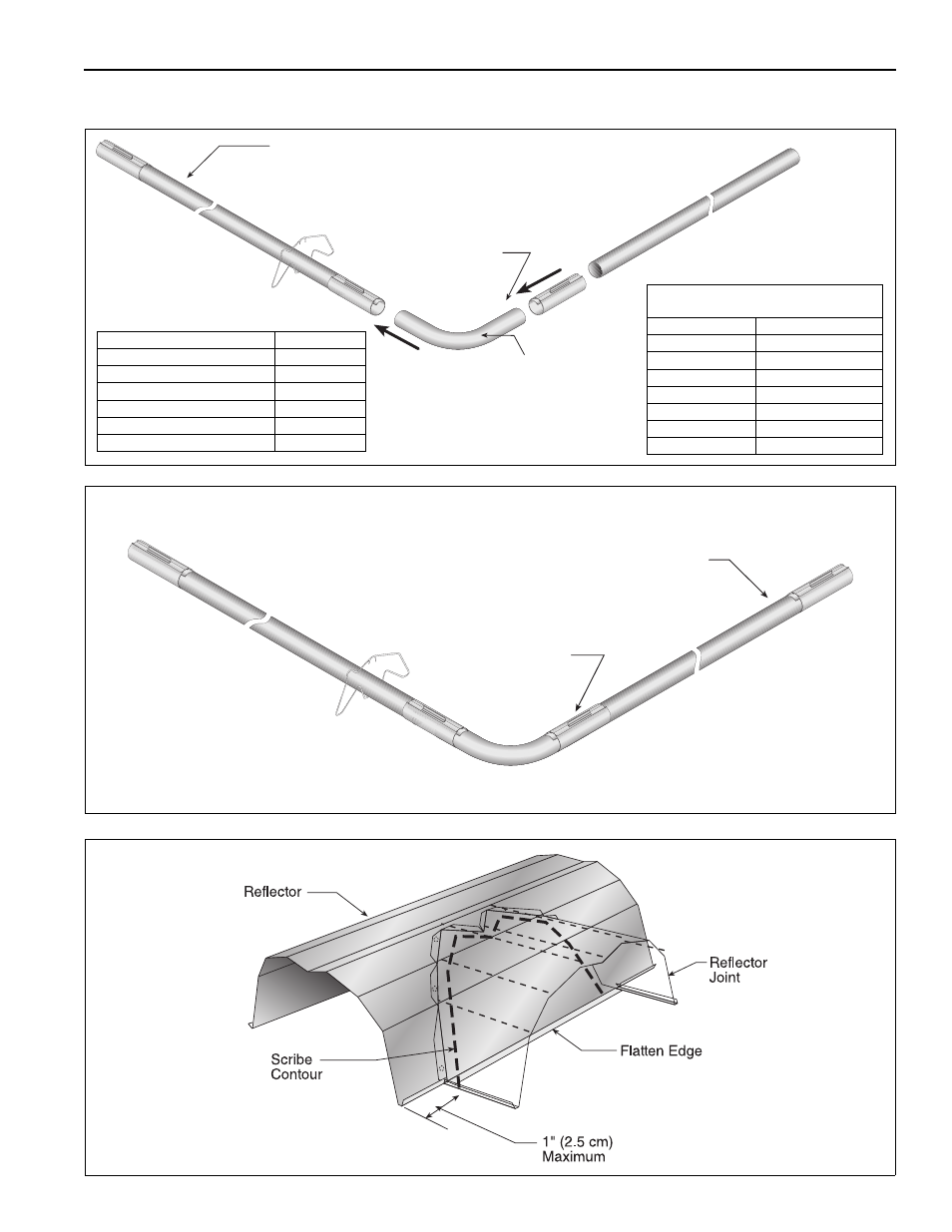
7.2 Elbow Package Configuration
Step 7.2.1 Elbow Installation
Step 7.2.2 Elbow Installation
Step 7.2.3 Reflector Joint Installation
Tube
90° Elbow
Coupling
Description
Part Number
Elbow Package
02718702
90° Elbow
01335801
Coupling
01312700
Reflector End Cap
02750800
Reflector Joint Piece
02750900
U-Clip Package
91107720
Minimum Distance Required Between
Burner and Elbow
Model
Minimum Distance
HE-40
-
HE-60
10' (3 m)
HE-80
10' (3 m)
HE-100
15' (4.5 m)
HE-125
15' (4.5 m)
HE-150
15' (4.5 m)
HE-175
15' (4.5 m)
Tube
Coupling
This manual is related to the following products: