Figure 12: venting, 10, figure 12, Through – Roberts Gorden Low Intensity Unitary Heater Designed for Harsh Environments HE-40 User Manual
Page 16
HE-S
ERIES
I
NSTALLATION
, O
PERATION
AND
S
ERVICE
M
ANUAL
10
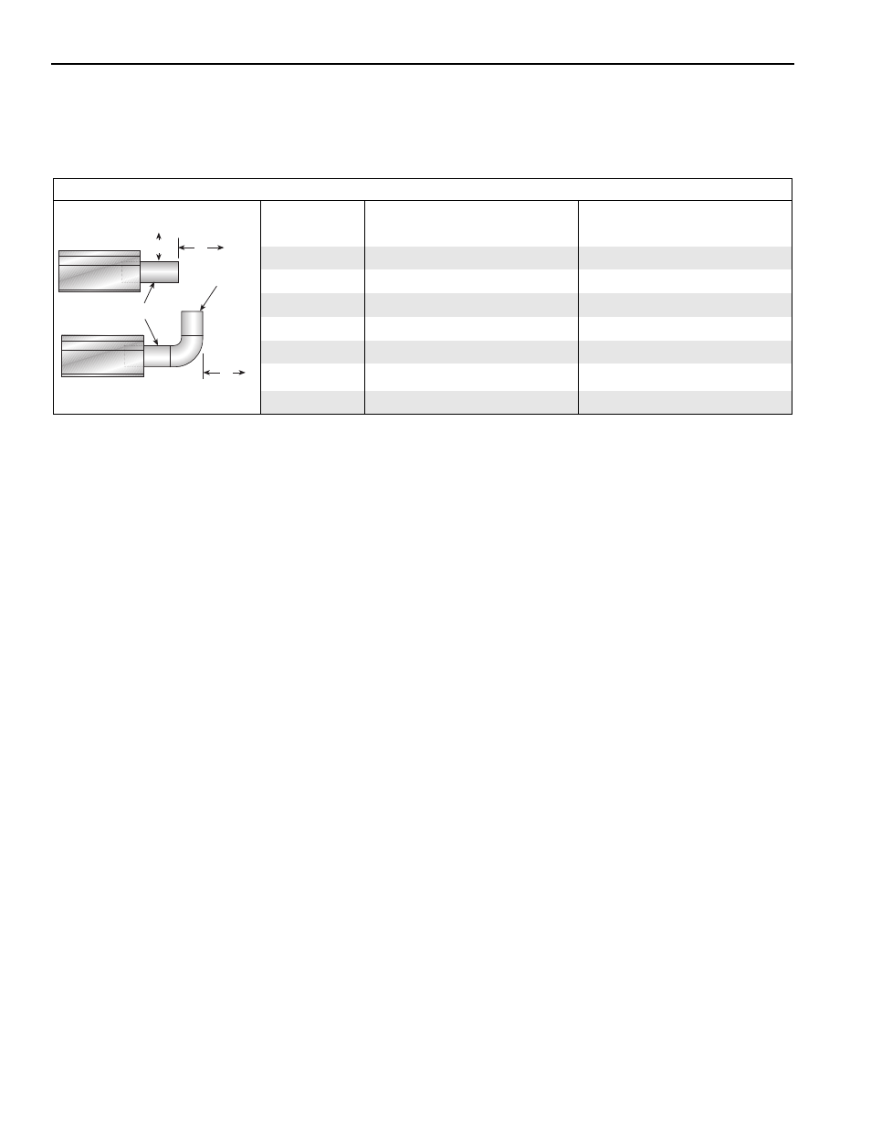
NOTE: 1. All dimensions are from the surfaces of all tubes, couplings and elbows.
2. Clearances B, C and D can be reduced by 50% after 25' (7.5 m) of tubing downstream
from where the burner and burner tube connect.
FIGURE 12: VENTING
(inches)
(centimeters)
Model
A
E
F
A
E
F
HE-40
14
18
18
36
46
46
HE-60
14
18
18
36
46
46
HE-80
20
24
18
51
61
46
HE-100
20
24
18
51
61
46
HE-125
20
24
18
51
61
46
HE-150
20
30
18
51
77
46
HE-175
20
30
18
51
77
46
Radiant Tubes
Vent
Pipes
Unvented
Vented
A
E
F
This manual is related to the following products: