Section 5: major components, Figure 13: major component descriptions – Roberts Gorden Low Intensity Unitary Heater Designed for Harsh Environments HE-40 User Manual
Page 18
HE-S
ERIES
I
NSTALLATION
, O
PERATION
AND
S
ERVICE
M
ANUAL
12
SECTION 5: MAJOR COMPONENTS
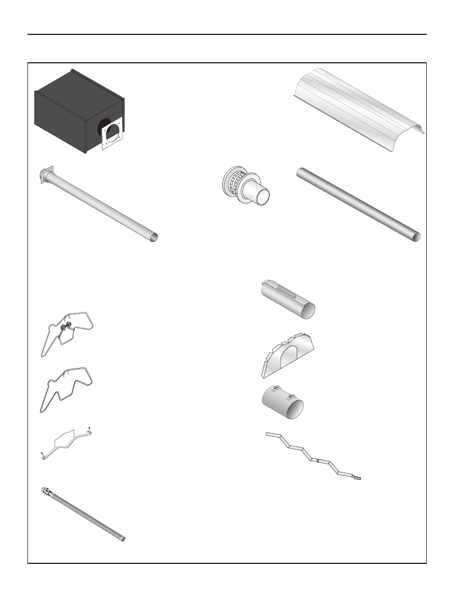
FIGURE 13: Major Component Descriptions
Burner with Tube Gasket
Must be installed with the
flame observation
window facing down.
Reflector
(Stainless Steel
or Aluminum)
Alternate
overlap as shown
on overview and
19, Figure 17. Minimum
overlap is 6" (16 cm).
Tube and Reflector Hanger
with Clamp Package
Position this hanger no more
than 4" (10 cm) away from
the burner.
Coupling Assembly
with Lock
Reflector End Cap
Punch out center
section to
accommodate tube.
Tube and Reflector Hanger
Suspend system from these
hangers.
Vinyl Coated Flex Gas
Line with Shut Off Cock
Tube
Heat Treated
Aluminized tube supplied
in 10' (3 m) lengths.
Burner Tube
Supplied in 10'
(3 m) lengths. Burner tube is
always the first tube after the burner.
Reflector Support Strap &
Wire Form
Turbulator
Turbulator must
be installed in the last
standard section of tube.
Turbulator is not required on the
HE-125/150/175. For installation
see Page 22, Section 6.5.
Vent Adapter
Vent Cap
Attach at flue end
and air inlet with
vent adapter,
where required.