Roberts Gorden Gas-Fired User Manual
Vantage, Gas-fired, low intensity unitary heater, Installation, operation & service manual
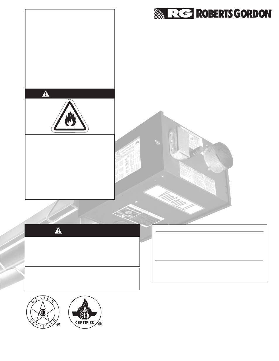
WARNING
Installation must be done by a contractor qualified
in the installation and service of gas-fired heating
equipment or your gas supplier.
Improper installation, adjustment, alteration, service
or maintenance can result in death, injury or
property damage. Read the Installation, Operation
and Service Manual thoroughly before installing or
servicing this equipment.
Installer
Please take the time to read and understand
these instructions prior to any installation.
Installer must give a copy of this manual to the owner.
Owner
Keep this manual in a safe place in order to provide
your serviceman with necessary information.
Roberts-Gordon LLC
1250 William Street
P.O. Box 44
Buffalo, New York 14240-0044
Telephone: +1.716.852.4400
Fax: +1.716.852.0854
Toll Free: 800.828.7450
www.rg-inc.com
www.radiantheaters.com
© 2012 Roberts-Gordon LLC
WARNING
FOR YOUR SAFETY
If you smell gas:
1. Open windows.
2. DO NOT try to light any appliance.
3. DO NOT use electrical switches.
4. DO NOT use any telephone in
your building.
5. Extinguish any open flame.
6. Leave the building.
7. Immediately call your local gas
supplier after leaving the building.
Follow the gas supplier’s
instructions.
8. If you cannot reach your gas
supplier, call the Fire Department.
Fire Hazard
Keep all flammable objects, liquids and
vapors the minimum required clear-
ances to combustibles away from
heater.
Some objects will catch fire or explode
when placed close to heater.
Failure to follow these instructions can
result in death, injury or property
damage.
Vantage
®
II
Gas-Fired, Low Intensity
Unitary Heater
Installation, Operation &
Service Manual
CTH2-40
CTH2-60
CTH2-80
CTH2-100
CTH2-125
CTH2-150
CTH2-175
P/N 130100NA Rev. M 02/12
Document Outline
- Vantage® II
- TABLE OF CONTENTS
- SECTION 1: Heater Safety
- SECTION 2: Installer Responsibility
- SECTION 3: Clearances to Combustibles
- 3.1 Required Clearances to Combustibles
- Note: 1. All dimensions are from the surfaces of all tubes, couplings and elbows. 2. Clearances B, C and D can be reduced by 50% after 25' (7.5 m) of tubing downstream from where the burner and burner tube connect.
- Note: 1. All dimensions are from the surfaces of all tubes, couplings and elbows. 2. Clearances B, C and D can be reduced by 50% after 25' (7.5 m) of tubing downstream from where the burner and burner tube connect.
- Note: 1. All dimensions are from the surfaces of all tubes, couplings and elbows. 2. Clearances B, C and D can be reduced by 50% after 25' (7.5 m) of tubing downstream from where the burner and burner tube connect.
- Note: 1. All dimensions are from the surfaces of all tubes, couplings and elbows. 2. Clearances B, C and D can be reduced by 50% after 25' (7.5 m) of tubing downstream from where the burner and burner tube connect.
- SECTION 4: National Standards and Applicable Codes
- SECTION 5: Major Components
- Figure 13: Major Component Descriptions
- 5.1 Standard Parts List
- Part No.
- Description
- CTH2-40
- CTH2-60
- CTH2-80
- CTH2-100
- CTH2-125
- CTH2-150
- CTH2-175
- 030XXXXX
- 1
- 1
- 1
- 1
- 1
- 1
- 1
- 02568200
- 1
- 1
- 1
- 1
- 1
- 1
- 1
- 130100NA
- 1
- 1
- 1
- 1
- 1
- 1
- 1
- 94273914
- 4
- 4
- 4
- 4
- 4
- 4
- 4
- 96411600
- 4
- 4
- 4
- 4
- 4
- 4
- 4
- 91201708
- 1
- 1
- 1
- 1
- 1
- 1
- 1
- 91317300
- 2
- 2
- 2
- 2
- 2
- 2
- 2
- *91412200
- 1
- 1
- 1
- 1
- 1
- *91412204
- -
- -
- -
- -
- -
- 1
- 1
- 03051503
- 1
- 1
- 1
- 1
- -
- -
- -
- 03051504
- 2
- 4
- 4
- 2
- -
- -
- -
- 03051505
- 1
- -
- -
- -
- -
- -
- -
- *Canadian Models: Rubber (Type 1) Gas Hoses available as an accessory. See Page 40, Section 9.
- Core Packages
- Extension Packages
- Hot Rolled
- Aluminized
- Hot Rolled
- Aluminized
- Part No.
- Description
- 20'
- (6m)
- 30'
- (9m)
- 40'
- (12m)
- 10'
- (3m)
- 20'
- (6m)
- 30'
- (9m)
- 40'
- (12m)
- 10'
- (3m)
- 20'
- (6m)
- 30'
- (9m)
- 40'
- (12m)
- 10'
- (3m)
- 20'
- (6m)
- 30'
- (9m)
- 40'
- (12m)
- 91409300
- 1
- 2
- 3
- -
- -
- -
- -
- 1
- 2
- 3
- 4
- -
- -
- -
- -
- 91409408
- -
- -
- -
- -
- 1
- 2
- 3
- -
- -
- -
- -
- 1
- 2
- 3
- 4
- 03051101
- -
- 1
- 1
- -
- -
- 1
- 1
- -
- -
- -
- -
- -
- -
- -
- -
- 03051601
- 1
- -
- -
- 1
- 1
- -
- -
- -
- -
- -
- -
- -
- -
- -
- -
- 01312700
- 1
- 2
- 3
- -
- 1
- 2
- 3
- 1
- 2
- 3
- 4
- 1
- 2
- 3
- 4
- 02750303
- 3
- 4
- 6
- 2
- 3
- 4
- 6
- 2
- 3
- 4
- 6
- 2
- 3
- 4
- 6
- 02750800
- 2
- 2
- 2
- 2
- 2
- 2
- 2
- -
- -
- -
- -
- -
- -
- -
- -
- 03090100
- 3
- 4
- 5
- 2
- 3
- 4
- 5
- 1
- 2
- 3
- 4
- 1
- 2
- 3
- 4
- 91907302
- 3
- 4
- 5
- 2
- 3
- 4
- 5
- 1
- 2
- 3
- 4
- 1
- 2
- 3
- 4
- 03050010
- 2
- 3
- 5
- 1
- 2
- 3
- 5
- 2
- 3
- 4
- 6
- 2
- 3
- 4
- 6
- 91107720
- 1
- 1
- 1
- 1
- 1
- 1
- 1
- 1
- 1
- 1
- 1
- 1
- 1
- 1
- 1
- 90502700
- 1
- 1
- 1
- 1
- 1
- 1
- 1
- -
- -
- -
- -
- -
- -
- -
- -
- 01318901
- 1
- 1
- 1
- 1
- 1
- 1
- 1
- -
- -
- -
- -
- -
- -
- -
- -
- Part Number
- Additional tubing length may be added to heater. Tubing must be heat-treated, aluminized or porcelain coated. Any additional tubing lengths are considered as vent length for length determination. Maximum venting length for minimum heater length is 45...
- Figure 13: Major Component Descriptions
- SECTION 6: Heater Installation
- Figure 14: Critical Hanger Placement
- Figure 15: Linear Heater Assembly Overview
- Figure 16: Linear Heater Layout Overview
- Figure 17: Linear Heater Layout Overview (Continued)
- Step 6.1 Burner Tube Installation
- Step 6.2 Tube Clamp Package Installation
- Step 6.3 Coupling and Tube Assembly
- Step 6.4 Turbulator Installation
- Step 6.5 Reflector Installation
- Step 6.6 Burner Installation
- SECTION 7: Optional Heater Accessories
- 7.1 U-Tube Configuration
- Figure 18: U-Tube Heater Assembly Overview
- Figure 19: U-Tube Heater Layout Overview
- Figure 20: U-Tube Heater Layout Overview (Continued)
- 7.2 Elbow Package Configuration
- Step 7.2.1 Elbow Installation
- Step 7.2.2 Elbow Installation
- Step 7.2.3 Reflector Joint Installation
- Step 7.2.4 Reflector Joint Installation
- Step 7.2.5 Reflector Joint Detail
- Figure 21: Reflector Joint Detail
- 7.3 Reflector Side Extension
- Step 7.3.1 Bracket Installation
- Step 7.3.2 Side Reflector Installation
- 7.4 Lower Clearance Shield Installation
- Step 7.4.1 Shield Support Strap Assembly
- 7.5 Two-Foot Decorative Grille Installation
- Step 7.5.1 Grille Installation
- Step 7.5.2 Frame Shield Installation
- Step 7.5.3 Reflector Side Extension Installation for Decorative Grilles
- Step 7.6.1 Silicone Cap Installation
- Step 7.6.2 Grille End Cap Installation
- Step 7.6.3 Grille Installation
- SECTION 8: Venting
- 8.1 General Venting Requirements
- 8.1.1 United States Requirements
- 8.1.2 Canadian Requirements
- Figure 22: Tube Termination
- 8.7 Horizontal Ventilation 4" (10 cm) Pipe
- 8.8 Vertical Ventilation 4" (10 cm) Pipe
- Step 8.9 Common Sidewall Venting
- 8.10 Common Vertical Venting
- 8.11.1 Length Requirements
- 8.11.2 Vertical Outside Air Supply for Single Heater Installation
- 8.11.3 Horizontal Outside Air Supply for Single Heater Installation
- 8.11.4 Vertical Outside Air Supply for Double Heater Installation
- 8.11.5 Horizontal Outside Air Supply for Double Heater Installation
- SECTION 9: Gas Piping
- SECTION 10: Wiring
- SECTION 11: Operation and Maintenance
- 11.1 Sequence of Operation
- 1. Turn the thermostat up. When the thermostat calls for heat, the SmartValve® II will energize. After a short period, power is supplied to the blower motor.
- 2. When the motor approaches nominal running RPM, the pressure switch closes and signals the ignition module/SmartValve® II.
- 3. The ignition module/SmartValve® II then energizes the hot-surface igniter for a timed warm-up period (approximately 45 to 60 seconds). After the warm-up period, the gas valve is energized.
- 4. If a flame is detected, the gas valve remains open and the igniter is de-energized. When the call for heat is satisfied and the system control mechanism de-energizes the burner line voltage supply, the gas is turned off.
- 5. If no flame is detected by the flame sensing rod, the igniter is de-energized and the module/ SmartValve® II will close and a purge period begins. After the purge, the module/SmartValve® II acts to power the igniter for a second warm-up period a...
- 6. If the flame extinguishes during operation, the igniter module will provide multiple trial sequences described in step 5. If ignition is not re-established, the module/SmartValve® II will lockout for one hour or until reset.
- 7. After lockout, reset by turning down thermostat for five seconds, and then raising it again to desired temperature, or by disconnecting power and then reconnecting.
- 11.2 To Shut Off Heater
- 11.3 To Start Heater
- 11.4 Pre-Season Maintenance and Annual Inspection
- 11.5 Maintenance Checklist
- 11.1 Sequence of Operation
- SECTION 12: Troubleshooting
- SECTION 13: Replacement Parts
- SECTION 14: General Specifications
- SECTION 15: The ROBERTS GORDON® VANTAGE® II Warranty