Step 6.4.2 coupling and tube assembly (continued), Step 6.5 turbulator installation, 5 turbulator installation – Roberts Gorden Low Intensity Unitary Heater Designed for Harsh Environments HE-40 User Manual
Page 28
HE-S
ERIES
I
NSTALLATION
, O
PERATION
AND
S
ERVICE
M
ANUAL
22
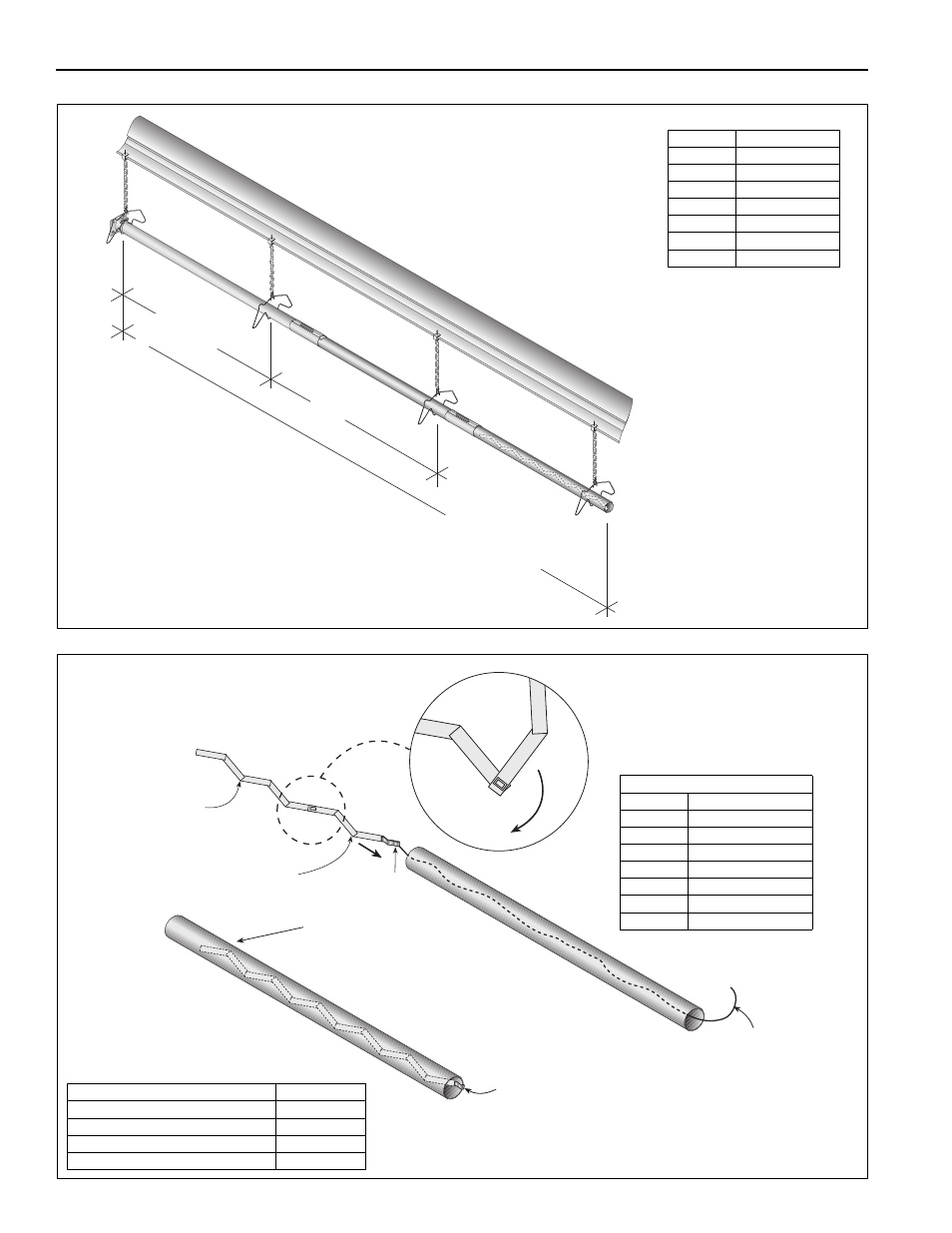
Step 6.4.2 Coupling and Tube Assembly (Continued)
Step 6.5 Turbulator Installation
10' ± 1'
(3 m ± .25 m)
Total Overall
Tube Length
7' 6" ± 1'
(2.3 m ± .25 m)
Model
Tube Length
HE-40
10' (3 m)
HE-60
20' (6 m)
HE-80
20' (6 m)
HE-100
30' (9 m)
HE-125
40' (12 m)
HE-150
50' (15 m)
HE-175
60' (18 m)
Hanging hardware shown
is for indoor installation
only.
15 for outdoor suspension
details.
Tw
ist
Pull String
Tab
Fold tab around outside
of tube nearest to the vent to hold turbulator
in place.
Turbulator
Section
Turbulator
Adapter
Turbulator Section
(stainless) used in HE-40
heaters must be in the section of
tube nearest to the burner.
Description
Part Number
Turbulator Adapter
03051503
Turbulator Section
03051504
Turbulator Section (Stainless)
03051505
Tube
91409XXX
Turbulator must be installed in
the last standard section of
tube. Turbulator is not required
on the HE-125/150/175.
Turbulator Installation
Model
Tube Section
HE-40
1st 10' Section
HE-60
2nd 10' Section
HE-80
2nd 10' Section
HE-100
3rd 10' Section
HE-125
N/A
HE-150
N/A
HE-175
N/A