Digital control circuitry, Figure 3-4. scxi-1120 digital control, Figure 3-4 – National Instruments SCXI-1120 User Manual
Page 54: Scxi-1120 digital control
Chapter 3
Theory of Operation
© National Instruments Corporation
3-7
SCXI-1120 User Manual
Digital Control Circuitry
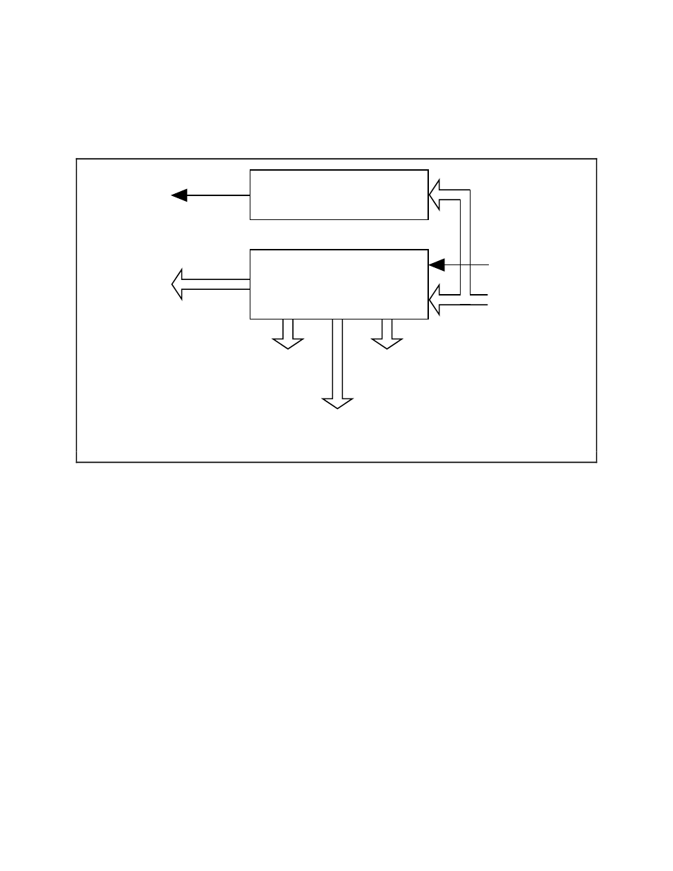
Figure 3-4 diagrams the SCXI-1120 digital control.
Module ID Register
Configuration
Register
Serial Data Out
Input Channel
Select
Output
Stage
Control
Hardware
Scan
Control
SCANCLK
Path
Control
Buffered
Serial Data In
Buffered Digital
Control Signals
Figure 3-4. SCXI-1120 Digital Control
The digital control section consists of the Configuration Register and the Module ID Register.
The Configuration Register is a two-byte, serial-in, parallel-out shift register. Data is received on
the MOSI line from either Slot 0 or the data acquisition board when SS* is enabled and D*/A
indicates data transfer (D*/A low). The Configuration Register provides channel selection and
configures the SCXI-1120 for scanning options. All the control bits are fed into a latch before
being routed to the rest of the module. The channel-select bits are taken directly from the shift
register. Complete descriptions of the register bits are given in Chapter 4, Register Descriptions.
Writes to the Configuration Register require the following steps:
1. SS* goes low, enabling communication with the board.
2. D*/A goes low, indicating that the information sent on the MOSI line is data.
3. The serial data is available on MOSI and SPICLK clocks it into the register.
4. SS* goes high and D*/A goes high, indicating an end of communication. This action latches
the Configuration Register bits.
When the SCXIbus is reset, all bits in the Configuration Register are cleared.