Digital interface, Figure 3-3, Digital interface circuitry block diagram – National Instruments SCXI-1120 User Manual
Page 53
Theory of Operation
Chapter 3
SCXI-1120 User Manual
3-6
© National Instruments Corporation
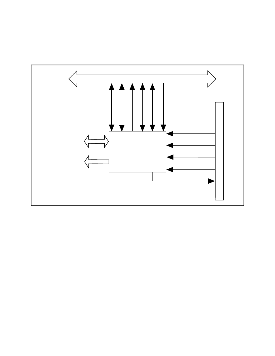
Digital Interface
Figure 3-3 shows a diagram of the SCXI-1120 and SCXIbus digital interface circuitry.
Digital
Interface
SCXIbus
Buffered Serial
Data
Buffered Digital
Signal Controls
SERDATIN
DAQD*/A
SLOT0SEL*
SERCLK
SERDATOUT
Rear
Signal Connector
MISO
SPICLK
INTR*
D*/A
MOSI
SS*
Figure 3-3. Digital Interface Circuitry Block Diagram
The digital interface circuitry is divided into a data acquisition section and an SCXIbus section.
The SCXI-1120 connects to the SCXIbus via a 4x24 metral receptacle and to the data acquisition
board via a 50-pin ribbon-cable header. The digital interface circuitry buffers the digital signals
from the data acquisition board and the SCXIbus and sends signals back and forth between the
data acquisition board and the SCXIbus.
- Instrument Driver NI-DMM (12 pages)
- 24-Bit Half/Full-Bridge Analog Input Module NI 9237 (36 pages)
- NI PXIe-8105 (76 pages)
- PXI NI 5401 (60 pages)
- Fieldpoint CFP-2210 (38 pages)
- NI 781xR (48 pages)
- NI 6233 (180 pages)
- 6508 PCI-DIO-96 (93 pages)
- PXI/CompactPCI Embedded Computer NI PXI-8108 (83 pages)
- NI 9233 (34 pages)
- NI USB-9219 (25 pages)
- GPIB-PC (262 pages)
- cFP-RTD-122 (15 pages)
- USB device 625x (23 pages)
- Isolated Analog Input Modules SCC-AI01 (18 pages)
- NI PCI-6111 (118 pages)
- NI USB-6008 (32 pages)
- PC-DIO-24 (75 pages)
- NI 9474 (31 pages)
- NI 6013 (109 pages)
- PXI-1428 (46 pages)
- NI PCI-5911 (51 pages)
- 2 SD Card Memory Module NI 9802 (16 pages)
- cFP-20xx (24 pages)
- NI USB-9234 (23 pages)
- NI 9871 (24 pages)
- Interface Device NI PCI-1426 (35 pages)
- AT E Series (184 pages)
- 9211A (19 pages)
- Module NI PXI-8250 (39 pages)
- 8330 Series (30 pages)
- NI PXIe-8360 (40 pages)
- Deterministic Ethernet Expansion Chassis NI 9144 (65 pages)
- NI 6509 (23 pages)
- NI MATRIXx Xmath (127 pages)
- NI 9481 (23 pages)
- Monochrome Image Acquisition Device NI 1410 (34 pages)
- VXI-1394 (74 pages)
- NI PXI-8104 (69 pages)
- NI 9235 (38 pages)
- 370620B-01 (17 pages)
- FP-RTD-124 (15 pages)
- VXI-USB (61 pages)
- NI PCI-8254R (45 pages)
- Interface Device NI PCI-8254R (16 pages)