Analog configuration, Grounding, shielding, and reference-mode selection, Jumper w46 – National Instruments SCXI-1120 User Manual
Page 23
Chapter 2
Configuration and Installation
© National Instruments Corporation
2-7
SCXI-1120 User Manual
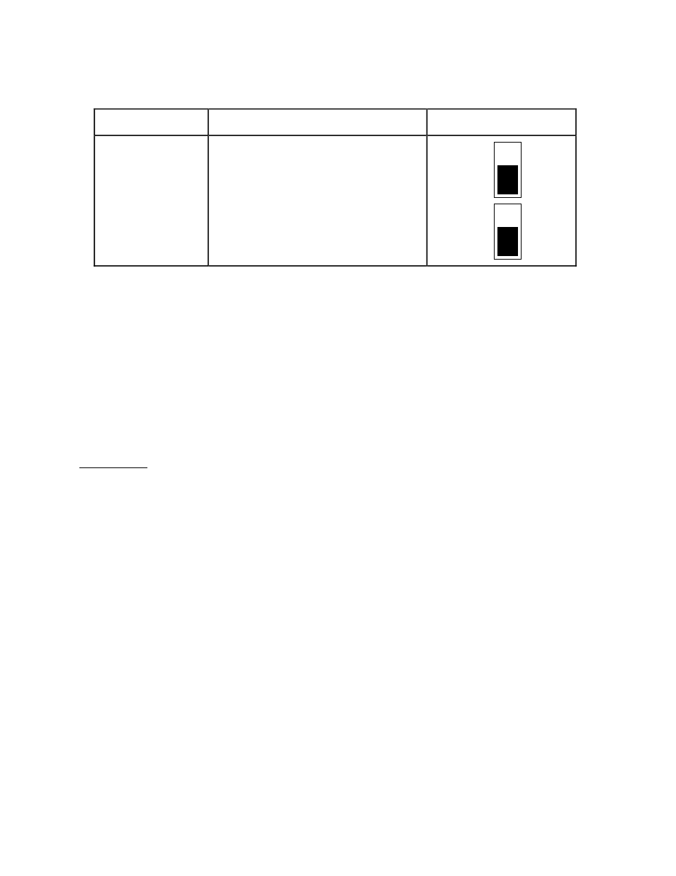
Table 2-1. Digital Signal Connections, Jumper Settings (Continued)
Jumper
Description
Configuration
W45
W44
Factory default
Factory default
(Revision A and B modules only)
•
•
•
3
2
1
•
•
•
3
2
1
Analog Configuration
The SCXI-1120 has 42 analog configuration jumpers.
Before starting, notice that the jumper configurations for each channel are similar; only the
jumper reference designator number changes. When you learn how to configure one channel,
you can configure the other channels as well.
Grounding, Shielding, and Reference-Mode Selection
Jumper W46
Position B-R0R1 is the parked position and the factory-default setting.
Position AB-R0 connects the analog reference to the analog output ground (pins 1 and 2 on the
rear signal connector). Select this configuration when using an RSE data acquisition board. You
should not use differential input data acquisition boards when jumper W46 is in the AB-R0
position.
Position AB-R1 connects the analog reference to the SCXIbus guard.
Position AB-R2 enables the Pseudodifferential Reference mode and connects the analog
reference to the OUTREF pin on the rear signal connector. Select this mode when the
SCXI-1120 has to operate with data acquisition boards that have a nonreferenced single-ended
input (NRSE). Do not use differential-input data acquisition boards when jumper W46 is in the
AB-R2 position.
Note: The SCXI-1120 will drive pins 4, 6, 8, 10, 12, 14, 16, and 18 on the rear signal connector,
although the SCXI-1120 is in pseudodifferential mode.