Figure 003-23, Mounting the pim to the rack parts – NEC NEAX2000 IVS ND-45492 User Manual
Page 66
ND-45492 (E)
CHAPTER 3
Page 49
Revision 2.0
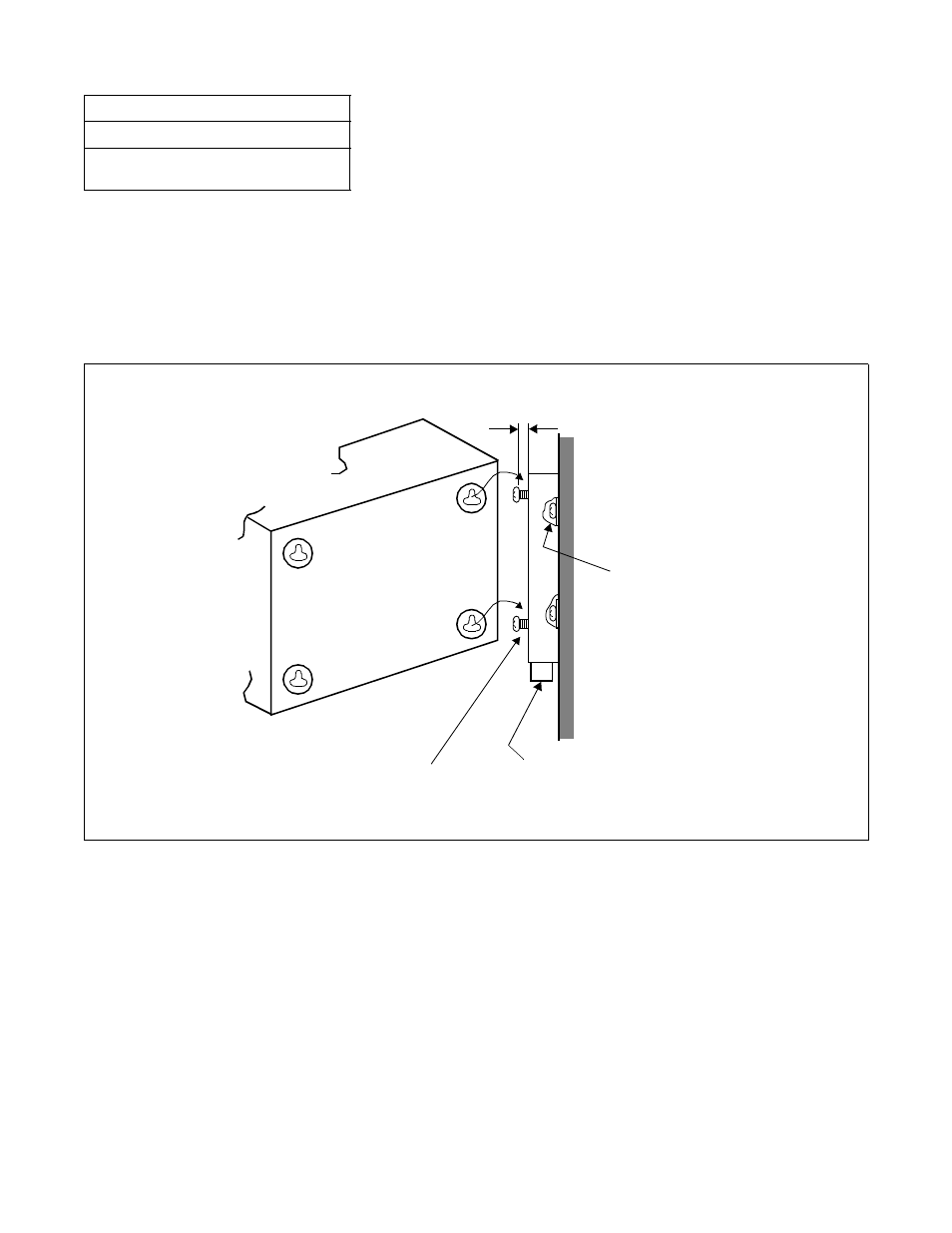
(3) Attach four M4 machine screws (provided) to the RACK PARTS as shown in
For proper mounting of each PIM, approximately 4 mm (0.2 inch) spacing should be provided between the
inner face of the M4 machine screw and the RACK PARTS front channel. See
(4) Align and insert the key hole slots of the rear cover of each PIM to the machine screws secured in step (3).
See
Figure 003-23 Mounting the PIM to the RACK PARTS
NAP 200-003
Sheet 27/37
Installation of Main Equipment
(PIM)
APPROX. 4 mm (0.2 inch)
(WALL)
SCREW-A (x 4)
RACK PARTS
M4 MACHINE SCREW-B (x 4)
(REAR COVER)
(LOCALLY PROVIDED)
(PROVIDED WITH RACK PARTS)