Chapter 2 general information, Trunking diagram, Chapter 2 – NEC NEAX2000 IVS ND-45492 User Manual
Page 20: General information, Figure 2-1, Pbx trunking diagram
ND-45492 (E)
CHAPTER 2
Page 3
Revision 2.0
CHAPTER 2
GENERAL INFORMATION
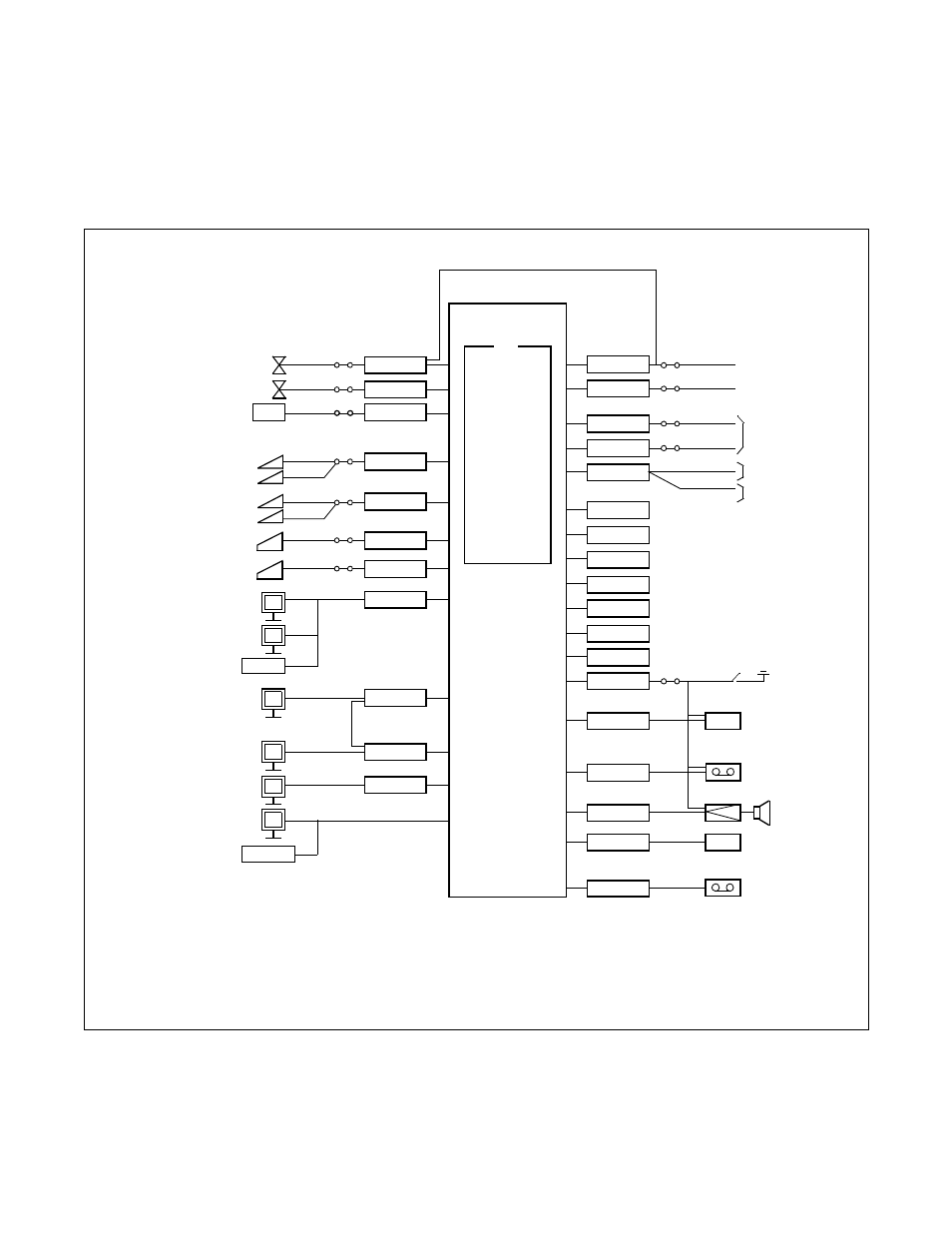
1. TRUNKING DIAGRAM
A typical trunking diagram for the PBX is shown in
Figure 2-1 PBX Trunking Diagram
MODEM
Note 1:
An external Modem is not required when the Built-In Modem on the MP is used.
Note 2:
The equipment marked with (*) is provided by the customer.
Note 3:
The MP functions marked with (**) are included in the PN-CP03 card only.
4W E&M
2W E&M
RS 232C
V.11
TCP/IP
V.11
RS-232C
RS 232C
LONG LINE STATION
SINGLE LINE
TELEPHONE
VOICE MAIL
SYSTEM
D
term
DSS
D
term
LONG LINE
DSS
SN610 ATTCON
SMDR
PMS
HOTEL
PRINTER
PC FOR OAI
AND ACD-MIS
PC FOR OAI
DTE
MAT
FROM LC
(FOR REMOTE
MAINTENANCE)
Note 1
DPC
ETHER
AP01
AP00
DLCC/DLCF
DLCB/DLCN
DLC
LCJ
LCD
AUC
PFT
MP
INCLUDING
SW
DTG
PBSND
16CFT
MLDT
PLO
MEM
MODEM
PBR**
TNT**
SMDR**
COT
AUC/DIT
ODT
ODT
DTI
CCH
DCH
PBR
DAT
PLO
MFR
CFT
DK
COT
COT
COT
COT/TNT
TNT
EXTERNAL HOLD
TONE(*)
(*)
SPEAKER(*)
AMP(*)
EXTERNAL HOLD
TONE(*)
ANNOUNCEMENT
MACHINE(*)
KEY(*)
6/10 PARTY CONFERENCE
DIGITAL
LINK
ISDN
NETWORK
TIE LINE
DID LINE
C.O. LINE
SN716 DESKCON
DLC