Netopia d-series dsl dsu status lights – Netopia D3232 IDSL User Manual
Page 18
2-18 User’s Reference Guide
N
N
N
Nee
e
etttto
o
o
op
p
p
piiiiaa
a
a D
D
D
D----S
S
S
See
e
errrriiiiee
e
essss D
D
D
DS
S
S
SLLL
L D
D
D
DS
S
S
SU
U
U
U ssssttttaa
a
attttu
u
u
ussss lllliiiig
g
g
gh
h
h
httttssss
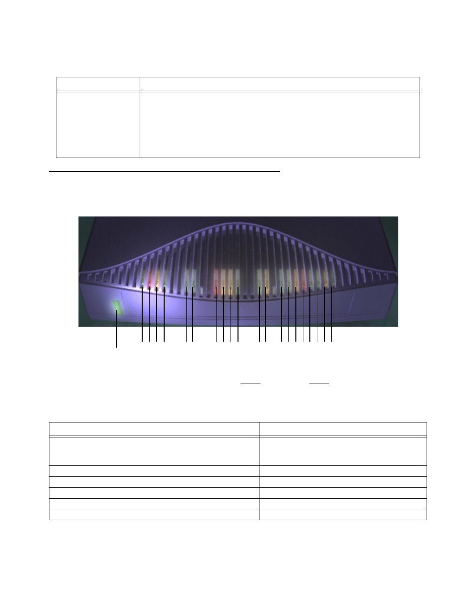
The figure below represents the Netopia D-Series status light (LED) panel.
Netopia D-Series LED front panel
The following table summarizes the meaning of the various LED states and colors:
8-por t Ethernet hub
Eight 10Base-T Ethernet jacks. You will use one of these to configure the
Netopia D-Series. For a new installation, use the Ethernet connection.
Alternatively, you can use the console connection to run console-based
management using a direct serial connection. You can either connect your
computer directly to any of the Ethernet por ts on the Netopia D-Series, or
connect both your computer and the Netopia D-Series to an existing Ethernet
hub on your LAN.
When this happens...
the LEDs...
The corresponding line passes super visor y traffic between
the Digital Subscriber Line Access Multiplexer (DSLAM) and
the Netopia D-Series
2 or 8 flashes
yellow
.
The WAN inter face is operational
3 or 9 is
green
.
The line is unavailable
3 or 9 flashes
red
.
The WAN on Channel 1 has carrier
4 or 10 is
green
.
Data is transmitted or received on the WAN on Channel 1
4 or 10 flashes
yellow
.
The WAN on Channel 2 has carrier
5 or 11 is
green
. (D3232 only)
Port
Description
2 3 4 5
6 7
8 9 10 11
12 13 14 15 16171819 20 21
Management
Ready
Channel 1
Link/Receive
Console
Auxiliar
y
Collision
Traffic
WAN 1
WAN 2
Ethernet
Power
1
Channel 2
Management
Ready
Channel 1
Channel 2