Identify the connectors and attach the cables, Filtering bridge mode, Dsu mode – Netopia D3232 IDSL User Manual
Page 16
2-16 User’s Reference Guide
You will need:
■
A Windows 95-, 98-, 2000-, or NT–based PC or a Macintosh computer with Ethernet connectivity for
configuring the Netopia D-Series. This may be built-in Ethernet or an add-on card, with TCP/IP installed and
configured. See
Chapter 4, “Configuring TCP/IP.”
■
An SDSL or IDSL wall outlet wired for a connection to a Competitive Local Exchange Carrier (CLEC) that
suppor ts Digital Subscriber Line connections.
IIIId
d
d
dee
e
en
n
n
nttttiiiiffffyyy
y tttth
h
h
hee
e
e cccco
o
o
on
n
n
nn
n
n
nee
e
ecccctttto
o
o
orrrrssss aa
a
an
n
n
nd
d
d
d aa
a
attttttttaa
a
acccch
h
h
h tttth
h
h
hee
e
e ccccaa
a
ab
b
b
bllllee
e
essss
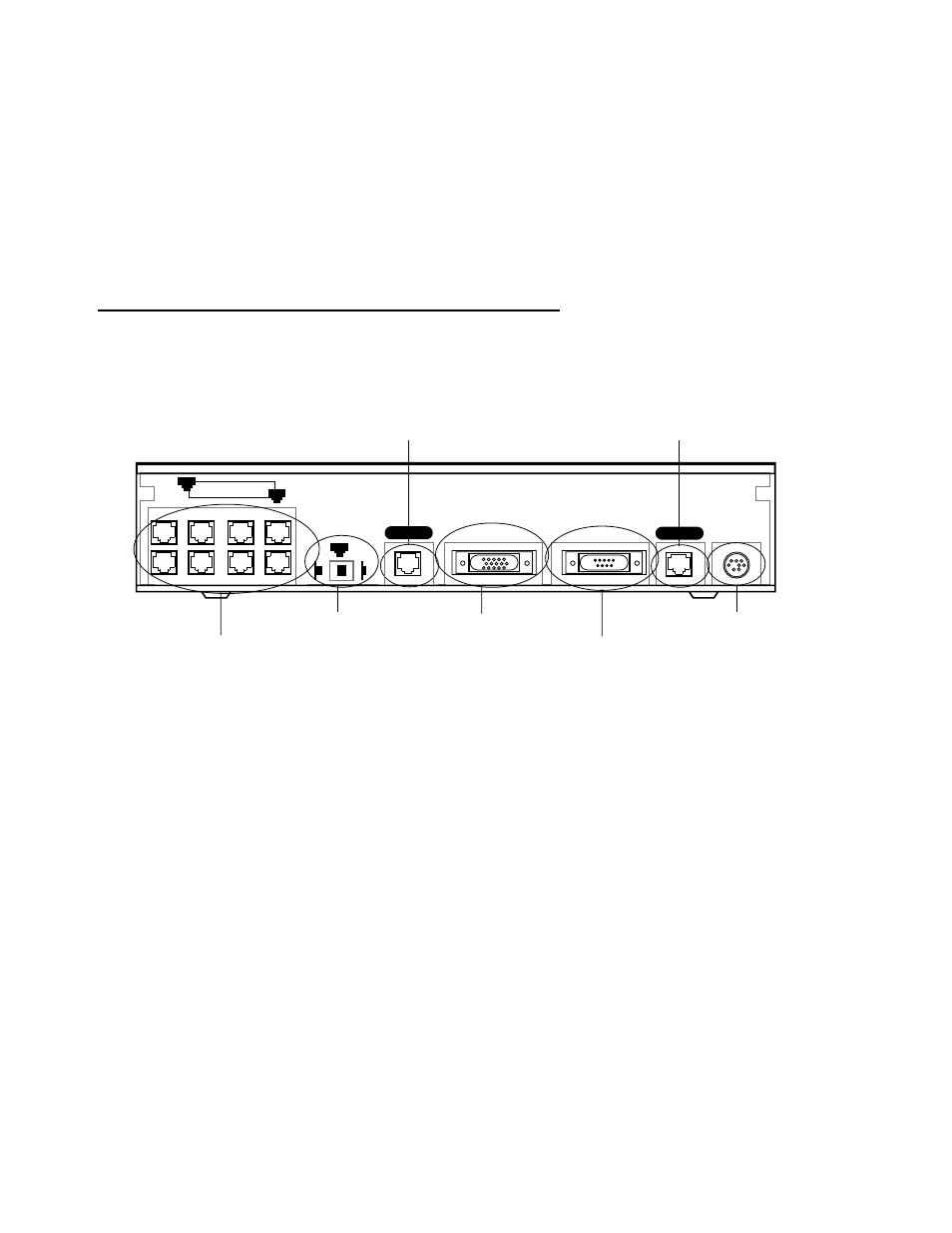
Identify the connectors and switches on the back panel and attach the necessar y Netopia D-Series cables.
The figure below displays the back of the Netopia D-Series DSL DSU.
Netopia D-Series DSL DSU back panel
FFF
Fiiiillllttttee
e
errrriiiin
n
n
ng
g
g
g B
B
B
Brrrriiiid
d
d
dg
g
g
gee
e
e m
m
m
mo
o
o
od
d
d
dee
e
e
1.
Connect the mini-DIN8 connector from the power adapter to the power por t, and plug the other end into an
electrical outlet.
2.
Connect one end one of the RJ-45 cables to the Line 1 por t, and the other end to your SDSL or IDSL wall
outlet.
3.
Connect one end of one of the RJ-45 Ethernet cables to any of the Ethernet por ts on the Netopia D-Series
and the other end to your computer or to your network.
(If you are connecting the Netopia D-Series to an existing Ethernet hub, use Ethernet por t #1 on the
Netopia D-Series and set the crossover switch to the
Uplink
position.)
You should now have: the power adapter plugged in; the Ethernet cable connected between the Netopia
D-Series and your computer or network; and the SDSL or IDSL cable connected between the Netopia
D-Series and the SDSL or IDSL wall outlet.
D
D
D
DS
S
S
SU
U
U
U m
m
m
mo
o
o
od
d
d
dee
e
e
1.
Connect the mini-DIN8 connector from the power adapter to the power por t, and plug the other end into an
electrical outlet.
Ethernet
Normal
Auxiliary
Console
Power
Line 1
8 por t Ethernet hub
Crossover switch
Line por t
Auxiliar y por t
Console por t
Power por t
8
1
1
Uplink
Line 2
Line por t